Electrical Machines II: UNIT IV: Starting and Speed Control of Three Phase Induction Motor
Types of Starters for Three Phase Induction Motor
The various types of starters based on the above two methods of reducing the starting current are, 1. Stator resistance starter 2. Autotransformer starter 3. Star-delta starter 4. Rotor resistance starter 5. Direct on line starter
Types of Starters for Three Phase Induction Motor AU
: May-05, 07, 08, 11, 12, 13, 14, 16,18, Dec.-04, 05, 10, 11, 12, 14, 15,16,17
From
the expression of rotor current it can be seen that the current at start can be
controlled by reducing E2 which is possible by supplying reduced
voltage at start or by increasing the rotor resistance R2 at start.
The second method is possible only in case of slip ring induction motors. The
various types of starters based on the above two methods of reducing the
starting current are,
1.
Stator resistance starter
2.
Autotransformer starter
3.
Star-delta starter
4.
Rotor resistance starter
5.
Direct on line starter
Let
us study the details of each of these starters.
1. Stator Resistance Starter
In
order to apply the reduced voltage to the stator of the induction motor, three
resistances are added in series with each phase of the stator winding.
Initially the resistances are kept maximum in the circuit. Due to this, large
voltage gets dropped across the resistances. Hence a reduced voltage gets
applied to the stator which reduces the high starting current. The schematic
diagram showing stator resistances is shown in the Fig. 7.3.1.
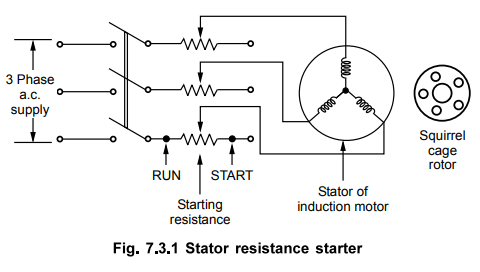
When
the motor starts running, the resistances are gradually cut-off from the stator
circuit. When the resistances are entirely removed from the stator circuit i.e.
rheostats in
RUN
position then rated voltage gets applied to the stator. Motor runs with normal
speed.
The
starter is simple in construction and cheap. It can be used for both star and
delta connected stator. But there are large power losses due to resistances.
Also the starting torque of the motor reduces due to reduced voltage applied to
the stator.
a.
Relation between Tst and TF. L .
We
know, P2 = T × ws
where T is torque produced and P2
is the rotor input at Ns.
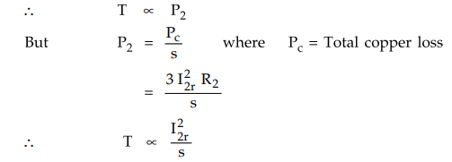
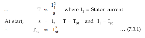
But
rotor current I2r and stator current are related to each other through
transformer action.
When
stator resistance starter is used, the factor by which stator voltage reduces
is say x< 1. The starting current is proportional to this factor x. So if Isc
is the normal current drawn under full rated voltage condition at start then,
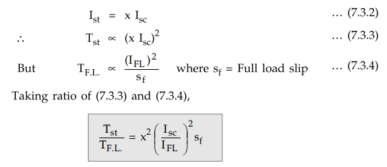
Key point As x < 1, it
can be seen that the starting torque reduces fey the fraction x2 due
to the stator resistance starter.
2. Autotransformer Starter
A
three phase star connected autotransformer can be used to reduce the voltage
applied to the stator. Such a starter is called an autotransformer starter. The
schematic diagram of autotransformer starter is shown in the Fig. 7.3.2.
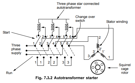
It
consists of a suitable change over switch.
When
the switch is in the start position, start the stator winding is supplied with
reduced voltage. This can be controlled by tappings provided with autotransformer.
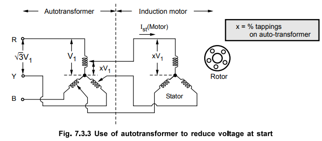
The
reduction in applied voltage by the fractional percentage tappings x, used for
an autotransformer is shown in the Fig. 7.3.3.
When
motor gathers 80 % of the normal speed, the change over switch is thrown into
run position.
Due
to this, rated voltage gets applied to stator winding. The motor starts
rotating with normal speed. Changing of switch is done automatically by using
relays. The power loss is much less in this type of starting. It can be used
for both star and delta connected motors. But it is expensive than stator
resistance starter.
a.
Relation between Tst and TF.L.
Let
x be the fractional percentage tappings used for an autotransformer to apply
reduced voltage to the stator.
So
if, Isc = Starting motor current at rated voltage
and Ist = Starting motor current with starter
then Ist = x Isc ... Motor side … (7.3.5)
But
there exists a fixed ratio between starting current drawn from supply Ist
(supply) and starting motor current Ist (motor) due to autotransformer, as
shown in the Fig. 7.3.4.
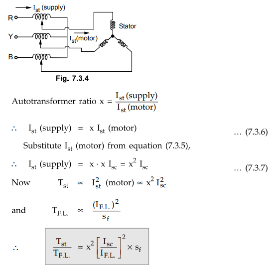
Key Point Thus starting
torque reduces by x2 where x is the transformation ratio.
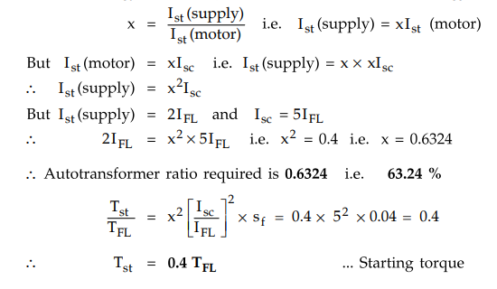
Example
7.3.1 A squirrel cage induction motor has a full load
slip of 5 %. The motor starting current at rated voltage is 6 times its full
load current. Find the tapping on the autotransformer starter which would give
full load torque at start. What would then be the supply starting current.
Solution
:
Starting
current at rated voltage = Isc
Let
x = Tapping on autotransformer
TF.L.
= Tst
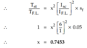
Thus
74.53 % tapping is required
Now Ist (supply) = x Ist
(motor) = x [x Isc] = x2 Isc
=
x2 x 6 IF.L = 3.33 IF.L
Thus
supply starting current is 3.33 times the full load current.
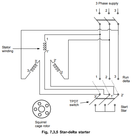
3. Star-Delta Starter
This
is the cheapest starter of all and hence used very commonly for the induction
motors. It uses Tripple Pole Double Throw (TPDT) switch. The switch connects
the stator winding in star at start. Hence per phase voltage gets reduced by
the factor 1 /√3. Due to this reduced voltage, the starting current is limited.
When
the switch is thrown on other side, the winding gets connected in delta, across
the supply. So it gets normal rated voltage. The windings are connected in
delta when motor gathers sufficient speed.
The
arrangement of star-delta starter is shown in the Fig. 7.3.5.
The
operation of the switch can be automatic by using relays which ensures that
motor will not start with the switch in Rim position. The cheapest of all and
maintenance free operation are the two important advantages of this starter.
While its limitations are, it is suitable for normal delta connected motors and
the factor by which voltage changes is 1 / √3 which can not be changed.
a. Ratio of Tst to TF.L.
We
have seen in case of autotransformer that if x is the factor by which the
voltage is reduced then,
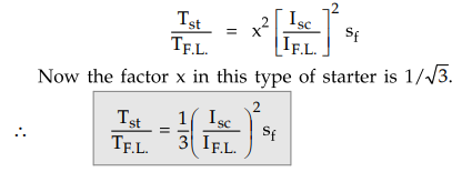
where
Isc = Starting phase current when delta connection with rated
voltage.
IF.L.
= Full load phase current when delta
connection.
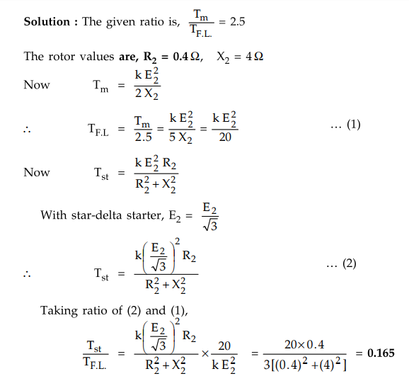
Example
7.3.2 A three phase induction motor has a ratio of
maximum torque to full load torque as 2.5 : 1. Determine the ratio of starting
torque to full load torque if star-delta starter is used. The rotor resistance
and standstill reactance per phase are 0.4 Ω and 4 Ω respectively.
Solution :
4. Rotor Resistance Starter
To
limit the rotor current which consequently reduces the current drawn by the
motor from the supply, the resistance can be inserted in the rotor circuit at
start. This addition of the resistance in rotor is in the form of 3 phase star
connected rheostat. The arrangement is shown in the Fig. 7.3.6.
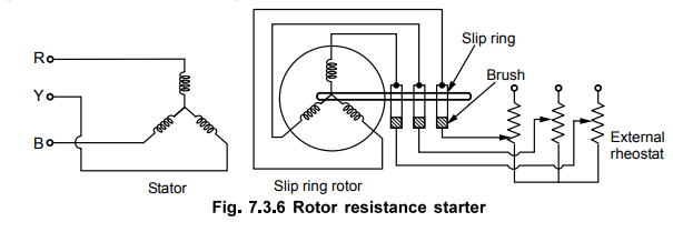
The
external resistance is inserted in each phase of the rotor winding through slip
ring and brush assembly. Initially maximum resistance is in the circuit. As
motor gathers speed, the resistance is gradually cutoff. The operation may be
manual or automatic.
We
have seen that the starting torque is proportional to the rotor resistance.
Hence important advantage of this method is not only the starting current is
limited but starting torque of the motor also gets improved. The only
limitation of the starter is that it can be used only for slip ring induction
motors as in squirrel cage motors, the rotor is parmanently short circuited.
5. Direct On Line Starter (D.O.L.)
In
case of small capacity motors having rating less than 5 h.p., the starting
current is not very high and such motors can withstand such starting current
without any starter. Thus there is no need to reduce applied voltage, to
control the starting current. Such motors use a type of starter which is used
to connect stator directly to the supply lines without any reduction in
voltage. Hence the starter is known as direct on line starter.
Though
this starter does not reduce the applied voltage, it is used because it protects
the motor from various severe abnormal conditions like over loading, low
voltage, single phasing etc.
The
Fig. 7.3.7 shows the arrangement of various components in direct on line
starter.
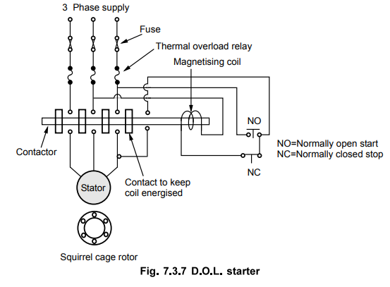
The
NO contact is normally open and NC is normally closed. At start, NO is pushed
for fraction of second due to which coil gets energised and attracts the
contactor. So stator directly gets supply. The additional contact provided,
ensures that as long as supply is ON, the coil gets supply and keeps contactor
in ON position. When NC is pressed, the coil circuit gets opened due to which
coil gets de-energised and motor gets switched OFF from the supply.
Under
over load condition, current drawn by the motor increases due to which there is
an excessive heat produced, which increases temperature beyond limit. Thermal
relays get opened due to high temperature, protecting the motor from overload
conditions.
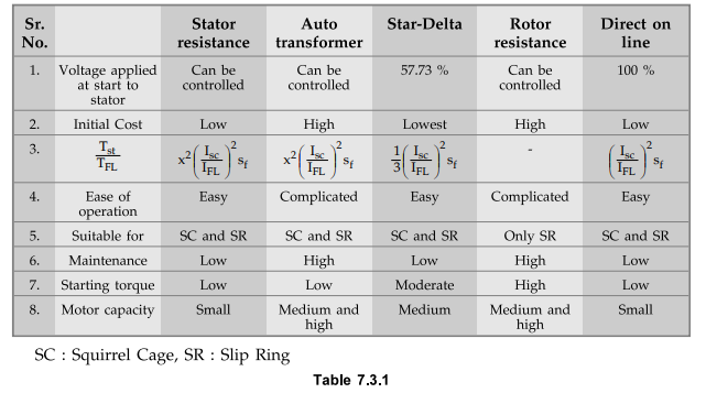
6. Comparison of Various Starters
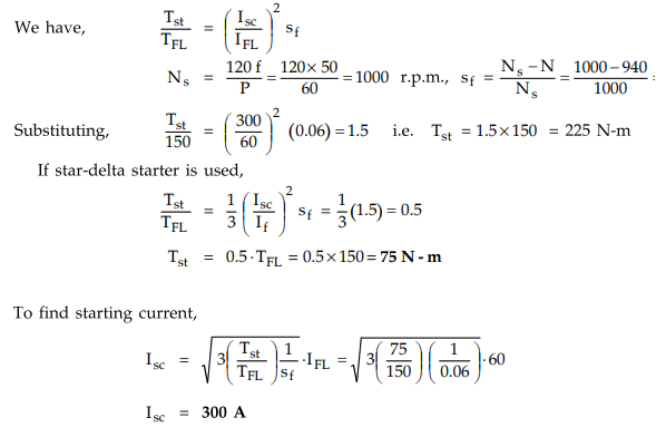
Example
7.3.3 A 3-phase, 6-pole, 50 Hz induction motor takes
60 A at full load speed of 940 rpm develops a torque of 150 N-m. The starting
current at rated voltage is 300 A. What is starting torque ? If a star/delta
starter is used determine the starting torque and starting current.
Solution
:
The
given values are, IF.L. = 60 A, P = 6 pole
N
= 940 r.p.m., TFL = 150 N-m, Isc = 300 A
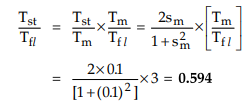
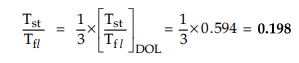
Example
7.3.4 A 3-phase squirrel cage induction motor has a
maximum torque equal to thrice the full load torque. Determine the ratio of
starting torque to full load torque if started by i) DOL starter ii) Star delta
starter. The maximum torque occurs at 0.1 slip.
Solution
:
i)
D.O.L. starter
ii)
With star-delta starter, the starting torque is one third of that obtained by
D.O.L. starter.
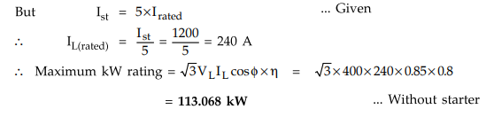
Example
7.3.5 A 3-phase, 400 V, distribution circuit is
designed to supply 1200 A. Assuming that three phase squirrel cage induction
motor has full load efficiency of 0.85 power factor 0.8 starting current is 5
times the rated current what is the maximum possible kW of motor if it is
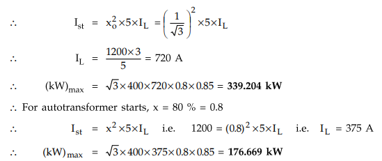
designed to use star-delta starter ? What is the maximum possible kW rating of
the motor if it is to be started using an autotransformer stepping down the
voltage to 80 % ? AU : Dec.-14, Marks 4
Solution
:
Maximum
possible permissible current that induction motor can take from the
distribution circuit is 1200 A at the time of starting.
If
it is designed to have star-delta starter, then star-delta starter is
equivalent to autotransformer with 57.8 % tapping. i.e. ratio (1/√3)
Example 7.3.6 A 3-phase, delta-connected cage type induction motor when connected directly to 400 V, 50 Hz supply takes a starting current of 100 A in each stator phase. Calculate :
i)
The line current for direct-on-line starting.
ii)
Line and phase starting currents for star-delta starting.
iii)
Line and phase starting currents for a 70 % tapping on auto-transformer
starting.
Solution
:
i)
In D.O.L. starter,
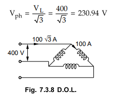
This
will produce a phase current of,
Iph
= 100 / √3 = 57.735 A
This
is because voltage is reduced by 1/√3, hence current will also reduce by 1/√3.
Starting
phase current = 57.735 A

In
start connection, IL = Iph .
Starting
line current = 57.735 A
iii)
70 % tapping on autotransformer starting
The
autotransformer is star connected. So phase voltage of autotransformer is 400/√3
= 230.94 V.
The
line voltage for delta connected stator is 0.7 × 400 = 280 V .
The
phase voltage for delta connected stator is 280 V.
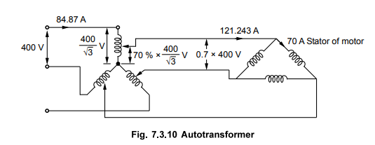
The 400 V circulates 100 A phase current hence
280 V will circulate a phase current of 280 / 400 × 100 = 70 A
Starting
phase current of motor = 70 A
Starting
line current of motor = √3 × 70 = 121.243 A
Supply
line current = 0.7 × 121.243 = 84.87 A
Example
7.3.7 The ratio of maximum torque to full-load torque
in a three phase squirrel cage induction motor is 2.2:1 Determine the ratio of
actual starting torque of full load torque for Direct starting, Star-delta
starting and Auto transformer starting with tapping of 70 %. The rotor resistance
and standstill reactance per phase are 0.5 Ω and 5 Ω. respectively.
Solution
:
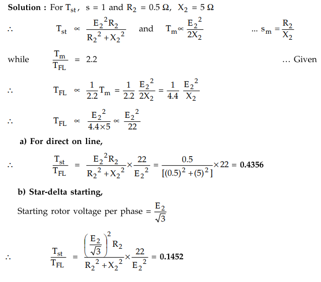
c)
Auto transformer starting,
Stator
voltage per phase = 0.7 times the voltage on direct on line.
i.e.
Rotor voltage at starting = 0.7 E2
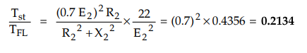
Example
7.3.8 A small squirrel-cage induction motor has a
starting current of six times the full load current and a full-load slip of
0.05. Find in pu of full-load values, the current (line) and starting torque
with the following methods of starting ((a) to (d)). a) Direct switching, b)
Stator-resistance starting with motor current limited to 2 p.u., c)
Auto-transformer starting with motor current limited to 2 p.u. and d) Y-delta
starting, e) What auto trnasformer ratio would give 1 pu starting torque ?
Solution
:
Let
F.L. current = 1 p.u., Ist = 6IFL, sfl;
= 0.05
a)
Direct switching
Tst = sfl I2st =
0.05 × 62 × (1 p.u.) = 1.8 p.u.
b)
Stator resistance starting
Ist
=2 p.u. (limited)
Tst
= 0.05 × (2)2 = 0.2 p.u.
c)
Autotransformer starting
Ist
(motor) = 2 p.u.
Let
× be the fraction by which the voltage applied to the motor is reduced.
Ist
= x Isc ... Isc
is starting current for full voltage.
Example
7.3.9 A three phase induction motor takes a starting
current which is 5 times full-load current at normal voltage. Its full-load
slip is 4 percent. What auto-tarnsformer ratio would enable the motor to be
started with not more than twice the full load current drawn from the supply ?
What would be the starting torque under this condition ? AU : May-14, Marks
8
Solution
:
Isc
= 5IFL, sf = 4% = 0.04
For
autotransformer starting, x be the ratio.
Ist
= Starting motor current with starter = × Isc
Examples
for Practice
Example
7.3.10 A cage type induction motor when started by
means of a star-delta starter takes 180 % of full load line current and
develops 35 % of full load torque at starting. Calculate the starting torque
and current in terms of full load values, if an autotransformer with 80 %
tappings were employed. UPTU : 2005-06
[Ans.:
Tst = 3.456 IfL, Tst = 0.6718 TfL]
Example
7.3.11 A cage induction motor when started by means of
a star-delta starter takes 180 % of full-load line current and develops 35 % of
full-load torque at starting. Calculate the starting torque and current in
terms of full-laod values, if an auto-transformer with 75 % tapping were
employed. UPTU : 2007-08
[Ans.:
Ist: 3.0375 Ifz,
Tst = 59.05 % Tfl]
Example
7.3.12 A 3o squirrel cage IM (SCIM) has maximum torque
equal to twice the full load torque. Determine the ratio of motor torque to its
full load torque, if it is started by:
i)
D.O.L. starter
ii)
Auto-transformer starter with 70 % tapping.
iii)
Star-delta starter.
The
per phase rotor resistance and per phase standstill reactance referred to
stator are 0.2 Ω and 2 Ω respectively. Neglect stator impedance. UPTU : 2011-12
[Ans.:
i) 0.396, ii) 0.194, iii) 0.132]
Example
7.3.13 A 3-phase induction motor in a short circuit
current equal to 4 times the full load current. Determine the starting torque
as a percentage of full load torque if full load slip is 2.5 %, for direct
starting and star-delta starting.
[Ans.
; 40 % of TFI, 13.33 % of TFI]
Review Questions
1. Explain the various
starting methods used for three phase induction motor. Analyse and compare
them.
2. Which are the
various starters used for three phase induction motors ? Explain star-delta
starter in detail.
3. Explain the
autotransformer starter used for three phase induction motors. AU : May-08,
Dec.-ll, 16 Marks 8
4. Describe a starter
suitable for a three phase slip-ring induction motor.
5. Explain the working
of rotor resistance starter with the help of neat circuit diagram.
6. Explain the working
of direct on line starter with the help of neat circuit diagram.
7. Compare the
performance of various types of starters used for squirrel cage induction
motors. AU : May-18, Marks 13
Electrical Machines II: UNIT IV: Starting and Speed Control of Three Phase Induction Motor : Tag: Engineering Electrical Machines - II : - Types of Starters for Three Phase Induction Motor
Related Topics
Related Subjects

Electrical Machines II
EE3405 Machine 2 EM 2 4th Semester EEE Dept | 2021 Regulation | 4th Semester EEE Dept 2021 Regulation