Linear Integrated Circuits: Unit V: Application ICs
Types of Voltage Regulator
Operating working principle, Functional Block Diagram
The basic voltage regulator in its simplest form consists of, 1. Voltage reference, VR 2. Error amplifier 3. Feedback network 4. Active series or shunt control element
Basic Voltage Regulator
The
basic voltage regulator in its simplest form consists of,
1.
Voltage reference, VR
2.
Error amplifier
3.
Feedback network
4.
Active series or shunt control element
The
voltage reference generates a voltage level which is applied to the comparator
circuit, which is generally error amplifier. The second input to the error
amplifier is obtained through feedback network. Generally using the potential
divider, the feedback signal is derived by sampling the output voltage. The
error amplifier converts the difference between the output sample and the
reference voltage into an error signal. This error signal inturn controls the
active element of the regulator circuit, in order to compensate the change in
the output voltage. Such an active element is generally a transistor.
Review Question
1. What are the blocks of basic voltage regulator ?
Types of Voltage Regulator
Depending
upon where the control element is connected in the regulator circuit, the
regulators are basically classified as,
1.
Series voltage regulator
2.
Shunt voltage regulator
Each
type provides a constant d.c. output voltage which is regulated.
1. Shunt Voltage Regulator
The
heart of any voltage regulator circuit is a control element. If such a control
element is connected in shunt with the load, the regulator circuit is called
shunt voltage regulator. The Fig. 5.5.1 shows the block diagram of shunt
voltage regulator circuit.
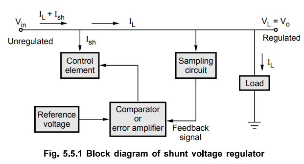
The
unregulated input voltage Vin, tries to provide the load current.
But part of the current is drawn by the control element, to maintain the constant
voltage across the load. If there is any change in the load voltage, the
sampling circuit provides a feedback
signal to the comparator circuit. The comparator circuit compares the feedback
signal with the reference voltage and generates a control signal which decides
the amount of current required to be shunted to keep the load voltage constant.
For example if the load voltage increases then the comparator circuit decides
the control signal based on the feedback information, which draws the increased
shunt current Ish. Due to this the load current IL
decreases, hence the load voltage decreases to its normal value.
Key
Point Thus the control element maintains the constant
output voltage by shunting the current, hence the circuit is called shunt
voltage regulator.
2. Series Voltage Regulator
If
in a voltage regulator circuit, the control element is connected in series with
the load, the circuit is called series voltage regulator circuit. The Fig.
5.5.2 shows the block diagram of series voltage regulator circuit.
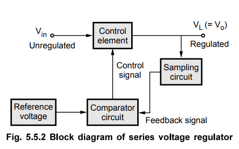
The
unregulated d.c. voltage is the input to the circuit. The control element,
controls the amount of the input voltage, that gets to the output. The sampling
circuit provides the necessary feedback signal. The comparator circuit compares
the feedback with the reference voltage to generate the appropriate control
signal.
For
example, if the load voltage tries to increase, the comparator generates a
control signal based on the feedback information. This control signal causes
the control element to decrease the amount of the output voltage. Thus the
output voltage is maintained constant.
Key
Point Thus, control element which regulates the load
voltage based on the control signal with the load and hence the circuit is
called series voltage regulator circuit.
Review Question
1. Explain the shunt and series voltage regulators.
Linear Integrated Circuits: Unit V: Application ICs : Tag: : Operating working principle, Functional Block Diagram - Types of Voltage Regulator
Related Topics
Related Subjects

Linear Integrated Circuits
EE3402 Lic Operational Amplifiers 4th Semester EEE Dept | 2021 Regulation | 4th Semester EEE Dept 2021 Regulation