Electromagnetic Theory: Unit V: Electromagnetic Waves
Uniform Plane Waves in Lossy Dielectric
Electromagnetic Waves
• Practically all the dielectric materials exhibit some conductivity (σ ≠ 0). So during analysis of the uniform plane waves through dielectric with some amount of conductivity, we cannot neglect o by assuming it to be zero.
Uniform Plane Waves in Lossy Dielectric
•
Practically all the dielectric materials exhibit some conductivity (σ ≠ 0). So
during analysis of the uniform plane waves through dielectric with some amount
of conductivity, we cannot neglect o by assuming it to be zero. Due to certain
conductivity, certain amount of loss in the medium takes place. Hence the wave
travelling through such medium gets attenuated (σ ≠ 0). Such dielectric is
called lossy dielectric. The results obtained for the lossy dielectric are
different as compared with the results for perfect dielectric medium.
•
Let us consider that a uniform plane wave travels in z-direction through the
lossy dielectric (σ ≠ 0). The wave equation for the electric field vector ![]() is given by,
is given by,

•
Using vector indentity on L.H.S. of equation (10.6.1), we get,

•
Now the wave travels in z-direction, then E is the function of z and t only,
hence equation (10.6.2) becomes,

Equation
(10.6.8) can be written as,
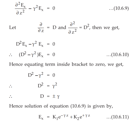
•
Where K1 and K2 are constants with respect to z but be
the functions of time t.

•
Substituting values of K1 and K2 in equation (10.6.11),
we get,

•
Above equation indicates the equation of electric field in the uniform plane
wave travelling through lossy dielectric in the z-direction. Assuming that wave
travels in +z-direction, the wave equation becomes,

Taking
real part of the term on R.H.S., we get,

•
Thus from equations (10.6.12), (10.6.13) and (10.6.14), the wave travels in
positive z-direction with velocity ω/β m/s. As the wave prograss, it gets attenuated
by the factor e-a. Thus a indicates the rate at which wave is
attenuated in amplitude during the propagation through lossy dielectric with
some finite non-zero conductivity.
•
The propagation constant ɤ in lossy dielectric is given by,
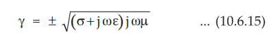
Rearranging
the terms,

•
From equation (10.6.16), it is clear that the propagation constant for lossy
dielectric medium is different than that for lossless dielectric medium, due to
the presence of radical factor. When σ becomes zero as in case with perfect
dielectric, the radical factor becomes unity and we can obtain the propagation
constant ɤ for perfect dielectric. It is also clear from equation (10.6.16)
that the attenuation constant a is not zero. By substituting the values of ω,
σ,µ and Ɛ, the attenuation constant (ɑ) and phase constant (β) may be
calculated. The presence of a indicates certain loss of signal in the medium,
hence such medium is called lossy dielectric.
•
When a wave propagates in a lossy dielectric, amplitude of the signal decays
exponentially due to the factor e-ɑz. For forward as well as
backward waves, the amplitude decays exponentially.
•
As σ is not zero, the intrinsic impedance becomes a complex quantity. It is given
by,

•
Being a complex quantity, h is represented in polar form as shown in above
equation. This angle 0n indicates phase difference between the electric and
magnetic fields. Thus in lossy dielectric, the electric and magnetic fields are
not in time phase.
•
The intrinsic impedance can be expressed as,

•
This angle depends on the properties of the lossy dielectric medium as well as
the frequency of a signal. For low frequency signal, ro becomes very small.
Then
θn
≈ π/4 rad
•
For very high frequency signals,
θn
≈ 0
•
Thus the range of θn for complete frequency range, from 0 to very
high frequency is 0 < θn < π/4.
Ex.
10.6.1 A lossy dielectric is characterized by Ɛr = 2.5, µr
= 4 and σ = 10-3 Ʊ/m at a frequency 10 MHz. Find, i) Attenuation
constant; ii) Phase constant; iii) Velocity of propagation ; iv) Wavelength and
v) Intrinsic impedance.
Sol.
:
For lossy dielectric,
µr
=4, Ɛr = 2.5, σ = 10-3 Ʊ/m, f = 10 MHz
i)
The propagation constant is given by,

1. Uniform Plane Wave in Practical Dielectric
•
As we have already studied, for perfect dielectric conductivity is zero (σ =
0). But for practical dielectric, conductivity is not zero ; but it is very
small. The condition for practical dielectric is that the loss in the signal is
very small i.e. σ < < jωƐ.
•
The propagation constant is given by,

•
Consider radical term, Mathematically using binomial theorem,

where
|x| < 1.
•
In our case |x| < 1 and n = 1/2, then
neglecting higher order terms, we can write,

•
Substituting above value for the radical term,

•
Comparing the real terms, the attenuation constant is given by,

•
Similarly comparing the imaginary terms, the phase constant is given by,

•
In general, the intrinsic impedance ɳ is given by,

•
As x = σ / jωƐ is very small as compared
to 1, so neglecting higher order terms,
(1
+ x)-n = 1 - nx
•
Using above result, the intrinsic impedance can be written as,

•
For practical dielectric material, the conductivity is very small. This
indicates that the loss in the signal is very small. Let us obtain the
condition which indicates whether the loss is small or not. Consider Maxwell's
equation,

•
We know that when the fields are time varying the partial derivative with
respect to time can be replaced by j ω.

•
Thus the ratio of the conduction current density to the displacement current
density is given by,

•
These two current density vectors point in same direction in space as shown in
the Fig. 10.6.1. From the expression of ratio of two current densities, it is clear
that displacement current density leads conduction current density by 90°.

•
The angle θ by which the displacement current density leads the total current
density is given by,
θ
= tan-1 σ / ωƐ
or
tan θ = σ / ωƐ
Key
Point : The term σ/ωƐ is called loss tangent of dielectric
and the angle θ is called loss angle.
•
When σ >> ωƐ, the loss tangent is
very high, thus a medium is said to be good conductor. When σ >> ωƐ, the loss tangent is also small,
thus a medium is said to be good dielectric. Hence any medium behaves as a good
conductor at low frequencies while exhibits the properties of lossy dielectric
at very high frequencies.
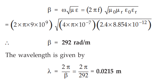
Ex.
10.6.2 A 9 GHz wave is propagating through a material that has a dielectric
constant of 2.4 and loss tangent of 0.005. Find a, β and the wavelength of the
material.
Sol.
:
The loss tangent for a dielectric is given by

For
given dielectric σ/jωƐ << 1, thus it is considered to be practical dielectric
For
practical dielectric

The
propagation constant is given by,
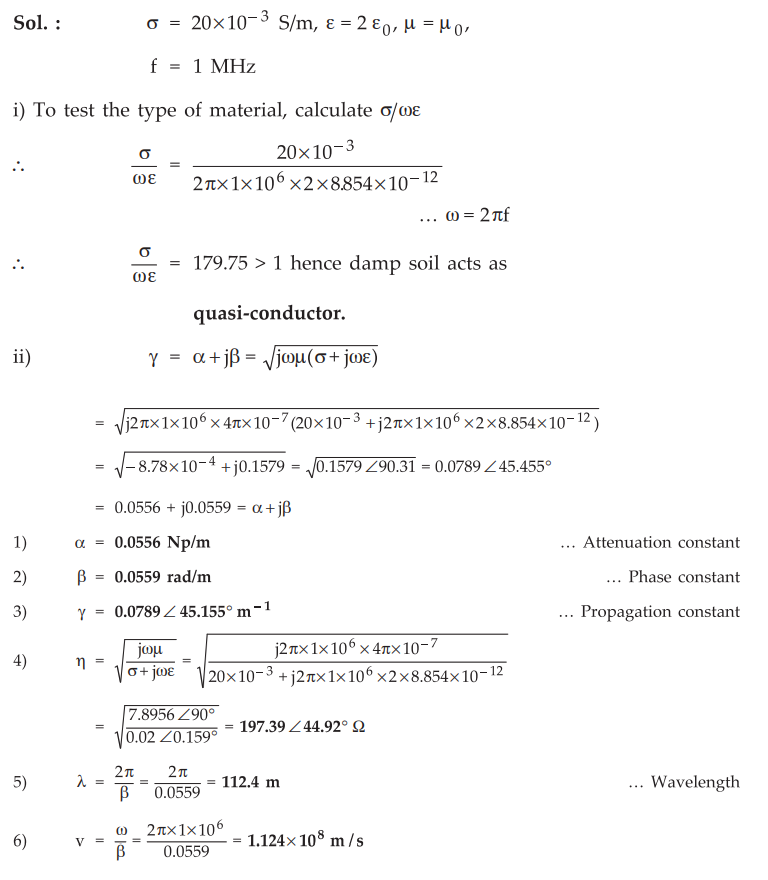
Ex.
10.6.3 A uniform plane wave of has σ = 20 × 10-3 S/m, Ɛ = 2 Ɛ0
is and μ = μ0 having a frequency of 1 MHz.
i)
Test the type of material
ii)
Calculate the following
1)
Attenuation constant
2)
Phase constant
3)
Propagation constant
4)
Intrinsic impedance
5)
Wave length
6)
Velocity of propagation
AU:
Dec.-18, Marks 13
Sol.
:
Examples for Practice
Ex.
10.6.4 A lossy dielectric has µr = 1, Ɛr = 50
and σ = 60 Ʊ/m d 15.9 MHz. Find a, 3 v and ’ if the uniform plane wave is
travelling through this medium.
[Ans.:
ɳ = 1.4465 ∠ 44.98°
Ω
Ex.
10.6.5 Calculate the attenuation constant and
phase constant for a uniform plane wave with frequency of 10 GHz in polythelene
for which µ = µ0, Ɛr, = 2.3 and σ = 2. 56 × 10-4 Ʊ/m.
[Ans.:
ɑ = 0.0554 Np/m and β = 317.84 rad/m]
Review Questions
1. What do you mean by practical dielectric ? What are the
values of propagation constant and intrinsic impedance ?
2. Explain the wave propagation in lossy dielectrics.
3. Explain the concept of 'Plane waves in lossy dielectrics.'
Deduce the results.
4. Describe the concept of electromagnetic wave propagation in a
linear, isotropic, homogeneous, lossy dielectric medium.
Electromagnetic Theory: Unit V: Electromagnetic Waves : Tag: : Electromagnetic Waves - Uniform Plane Waves in Lossy Dielectric
Related Topics
Related Subjects

Electromagnetic Theory
EE3301 3rd Semester EEE Dept | 2021 Regulation | 3rd Semester EEE Dept 2021 Regulation