Digital Logic Circuits: Unit III: (c) Shift Registers
Universal Shift Register
Principle of operation, Logic Diagram, Truth Table
• A register capable of shifting in one direction only is a unidirectional shift register. • A register capable of shifting in both directions is a bidirectional shift register.
Universal Shift Register
•
A register capable of shifting in one direction only is a unidirectional shift
register.
•
A register capable of shifting in both directions is a bidirectional shift
register.
•
If the register has both shifts (right shift and left shift) and parallel load
capabilities, it is referred to as universal shift register.
•
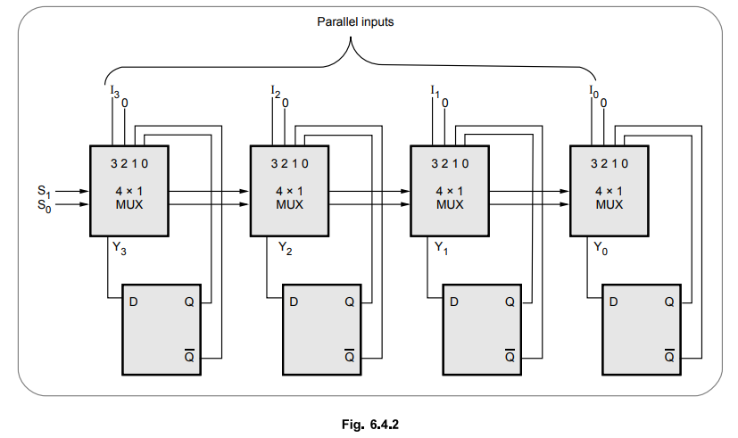
The Fig. 6.4.1 shows the 4-bit universal shift register.

•
It consists of four flip-flops and four multiplexers.
•
The four multiplexers have two common selection inputs S1 and S0,
and they select appropriate input for D flip-flop.
•
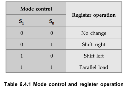
The Table 6.4.1 shows the register operation depending on the selection inputs
of multiplexers.
•
When S1S0 = 00, input 0 is selected and the present value
of the register is applied to the D inputs of the flip-flops. This results no
change in the register value.
•
When S1S0 = 01, input 1 is selected and circuit
connections are such that it operates as a right shift register.
•
When S1S0 = 10, input 2 is selected and circuit connections
are such that it operates as a left shift register.
•
Finally, when S1S0 = 11, the binary information on the
parallel input lines is transferred into the register simultaneously and it is
a parallel load operation.
Ex.
6.4.1 Draw the logic diagram of a 4-bit shift register with four D flip-flops
and four 4x1 multiplexer with mode selection inputs Sx and S0. The register
operates as follows.
AU
: CSE : Dec.-08, Marks 12
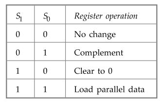
Sol.
: The Fig. 6.4.2 shows the register that does the given operations.
Review Questions
1. What is meant by universal shift register? Explain the
principle of operation of 4-bit universal shift register.
2. Explain the operation of universal shift register with neat block diagram.
Digital Logic Circuits: Unit III: (c) Shift Registers : Tag: : Principle of operation, Logic Diagram, Truth Table - Universal Shift Register
Related Topics
Related Subjects

Digital Logic Circuits
EE3302 3rd Semester EEE Dept | 2021 Regulation | 3rd Semester EEE Dept 2021 Regulation