Electric Circuit Analysis: Chapter - 2: Network Theorems - DC
Unsolved Problems
Network Theorems - DC | Electric Circuit Analysis
Electric Circuit Analysis : Chapter - 2 : Network Theorems - DC : Unsolved Problems
UNSOLVED PROBLEMS
1.
Find (a) the current, IL (b) the load voltage VL and (c)
the load power PL in the circuit of figure by the principle of
Superposition.
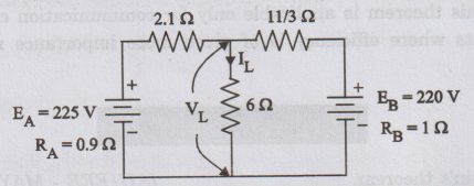
[Ans: IL = 28.5 A, V1 =
171 V, PL = 4873.5 W]
2.
Find the current in the 150 2 load resistor by using Superposition theorem.
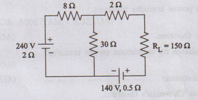
[Ans:
IL = 0.25 A]
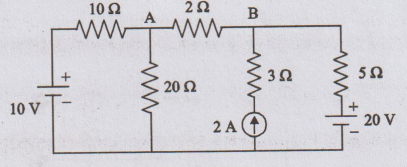
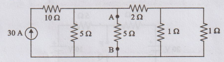
3.
For the circuit shown in figure, determine the current in 10 2 resistor by
applying Superposition theorem.

[Ans: 2.353 A]
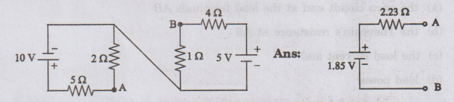
4.
Find the voltage across the 2 2 resistor in figure, by using the Superposition
theorem.
10
V
[Ans:
-3.41 V]
5.
Find the current in the 150 2 load resistor by using Thevenin's theorem.
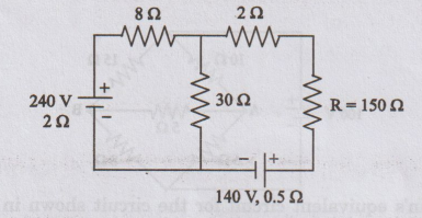
[Ans:
0.25 A]
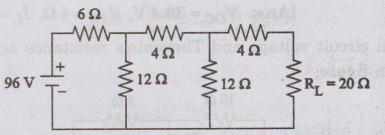
6.
For the circuit shown in figure, determine
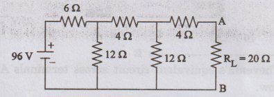
(a)
the open circuit emf at the load terminals AB
(b)
the Thevenin's resistance at AB
(c)
the load current and
(d)
load power
[Ans:
VOC = 38.4 V, RTh = 4, Ω
IL = 1.333 A, PL = 35.6 W]
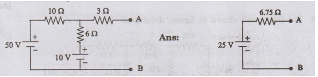
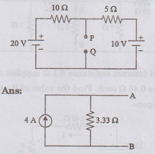
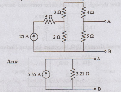
7.
Determine open circuit voltage and Thevenin's resistance across AB for the
given circuit shown in figure.
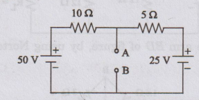
[Ans: VOC = 33.3 V, RTh
= 3.33 Ω]
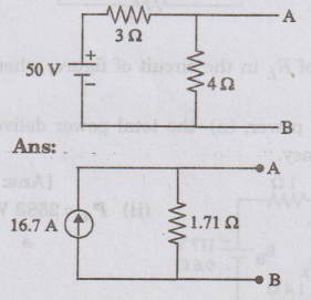
8.
Use Thevenin's theorem to find the current in 32 resistor in figure given
below.
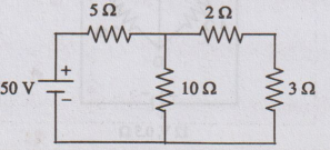
[Ans:
4 A]
9. Use Thevenin's theorem to find the current through the 5 2 resistor in figure given below.
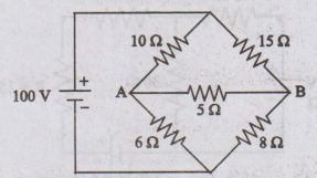
[Ans: 0.193 A]
10.
Find the Thevenin's equivalent circuit for the circuit shown in figure given
below. AS.0
11.
Determine the Thevenin's equivalent circuit across terminals AB for the circuit
in figure given below.
12.
Determine load current by using Norton's theorem for the given circuit.
[Ans: 1.333 A]
13.
Find the current in the arm BD of figure, by using Norton's theorem.
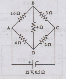
[Ans: 0.5 A]
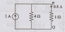
14.
Draw the Norton's equivalent at terminals P Ω for the circuit of given figure.
Hence find the current flow through in a 1 Ω resistor connected between P and
Q.
15.
Determine the current through 10 2 resistance by using Norton's theorem.
[Ans: 2.353 A]
16.
Determine Norton's equivalent circuit at terminals PQ for the circuit shown in
figure.
17.
Determine Norton's equivalent circuit for the circuit shown in figure.
18.
Determine Norton's equivalent circuit for the given circuit shown in figure.
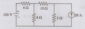
19.
Determine the current flowing through the 52 resistor in the circuit shown in
figure by using Norton's theorem.
[Ans: 7.51 A]
20. A battery of 120 V and internal resistance 0.12 supplies a load resistor R through two wires of resistance 0.45 2 each. Find the value of RL which consumes maximum power as shown in figure.
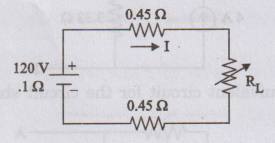
[Ans: R2 = 1
Ω]
21.
Find the ohmic value of RL in the circuit of figure, when its power
is a maximum. Find also.
(i)
the maximum load power. (ii) the total
power delivered by both the batteries. (iii) the overall efficiency.
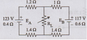
[Ans: (i) 2400 W (ii) PA=2583 W, PB
= 2223 W (iii) 50%]
22.
A resistor R is connected in parallel with another of value of 20 Ω. This
combination is connected to a 120 V source through a 4 Ω line resistor. For
what value of R will its power be a maximum. Find this maximum power.
[Ans: 3.33 Ω, 750 W]
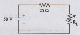
23.
In the circuit shown in figure, determine the value of load resistance when the
load resistance draws maximum power. Also find the value of the maximum power.
[Ans:
25 Ω, 25 W]
24.
Determine the maximum power delivered to the load in the circuit shown in
figure.
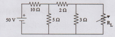
[Ans: 4.67 W]
25.
Determine the load resistance to receive maximum power from the source; also
find the maximum power delivered to the load in the circuit shown in figure.
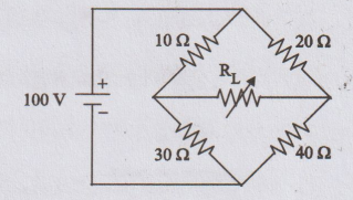
[Ans: 20.83 Ω 2, 0.833 W]
Electric Circuit Analysis: Chapter - 2: Network Theorems - DC : Tag: : Network Theorems - DC | Electric Circuit Analysis - Unsolved Problems