Electric Circuit Analysis: Chapter - 1: Basic Circuit Analysis - DC
Unsolved Problems with Answer
Basic Circuit Analysis - DC | Electric Circuit Analysis
Electric Circuit Analysis : Chapter - 1 : Basic Circuit Analysis - DC : Electric Circuit Analysis
UNSOLVED PROBLEMS
1.
A coil consists of 2000 turns of copper wire having a cross-sectional area of
0.8 mm2. The mean length per turn is 80 cm, and the resistivity of
copper is 0.2 μ Ω - m. Find the resistance of the coil.
[Ans:
R= 40 Ω]
2.
The resistance of a conductor 1 mm2 in cross-section and 20 m long is 0.346 Q.
Determine the specific resistance of the conductor material.
[Ans:
p = 1.73 × 10⁻⁸ Ω-m]
3.
Calculate the filament resistance in a (i) 100 W, 250 V lamp (ii) 1.5 kW, 250V
iron.
[Ans:
(i) 625 Ω (ii) 41.33 Ω]
4.
A 20 Ω resistor is connected in series with an unknown resistor to a 200V
supply. If the current drawn in 4A, find the value of the unknown resistor and
power in each resistor.
[Ans:
30 Ω, 320 W, 480 W]
5.
Two coils connected in parallel across 100V supply draw a total current of 9A.
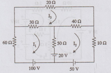
The power dissipated in one coil is 500W. Find the resistance of the two coils.
[Ans:
20 Ω, 25 Ω]
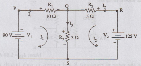
6.
A resistor, R is connected in series with a parallel combination of two
resistances of 12 2 and 6 2. This circuit takes 150W power from a supply of
30V. Calculate the value of R.
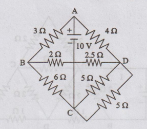
[Ans:
R = 2 Ω]
7.
A filament lamp is rated 100W and 110V. Find the value of the resistance to be
connected in series with this lamp so that it can be operated on a 230V supply.
What is the power loss in the resistor?
[Ans:
R= 132 Ω; P= 109.1 W]
8.
Across a 230V supply terminals in a house, an electric iron having a resistance
of 50 Ω and incandescent lamps of resistances 450 Ω and 800 Ω respectively are
connected. Find the total current and power taken from the supply mains.
[Ans:
I= 5.163 A; P = 1135.86 W]
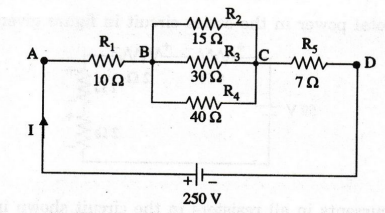
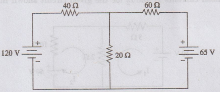
9.
In the circuit shown in figure, find the current in the 40 Ω resistor.
[Ans:
2A]
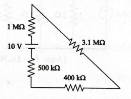
10.
What is the current in the circuit shown in figure? Determine the voltage
across each resistor.
[Ans:
I = 2 μA, V1 M = 2 V, V3.1 M = 6.2 V V400 k =
0.8 V, V500 k = 1 V]
11.
In the circuit given in figure, find (a) the current I, and (b) the voltage
across 30 Ω
[Ans: I = 1.5 A, V30 Ω = 45 V]
12.
What is the voltage across the 10 Ω resistor in figure given below.
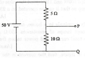
[Ans:
33.3 V]
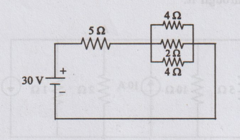
13.
Determine the total power in the series circuit in figure given below.
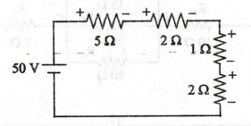
[Ans: 250 W]
14.
Determine the currents in all resistors in the circuit shown in figure.
[Ans: I1 = 14.705 A, I2
= 29.41 A, I3 = 5.88 A]
15.
For the circuit shown in figure, find the voltage across the 10 2 resistor and
the current passing through it.
[Ans: V10 = 2.78 V, I10 =
0.278 A]
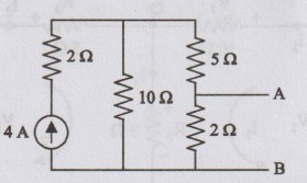
16.
Determine the current through resistance R3 in the circuit shown in
figure.
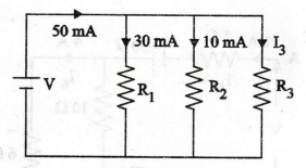
[Ans: I3 = 10 mA]
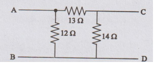
17.
Determine the equivalent resistance between points C and D of the circuit shown
in figure.
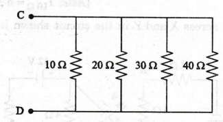
[Ans:
4.8 Ω]
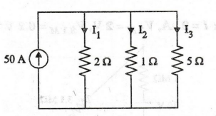
18.
Determine the current through each resistor in the circuit shown in figure.
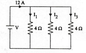
[Ans: I1 = 4 A, I2 = 4 A, I3
= 4A]
19.
Determine the current in the circuit shown in figure.
[Ans:
5A]
20.
Find the current in the 10 Ω resistance, V1 and source V in
the circuit shown in figure.
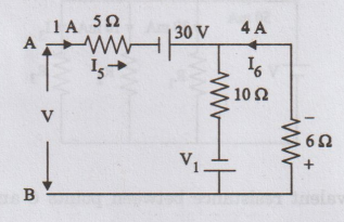
[And:
I10 Ω = 5A, V1 = 74V, V = 149 V]
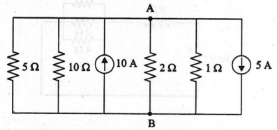
21.
What is the voltage across X and Y in the circuit shown in figure?
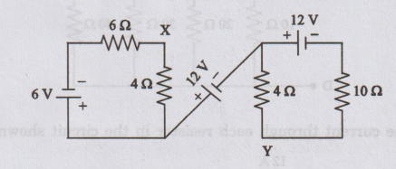
[Ans:
VXY = 13.04 V]
22.
Determine the current delivered by the source in the circuit shown in figure.
[Ans: I = 28.57 A]
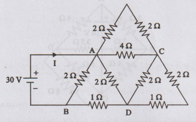
23.
Determine the current in the 10 2 resistance and find voltage across A and B in
the circuit shown in figure.
[Ans: I10 = 1.65 A, VAB
= 4.7 V]
24.
Determine the value of resistance R and current in each branch when the total
current taken by the circuit shown in figure is 6A.
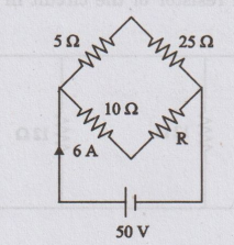
[Ans: I30 = 1.66 A, I10+
R = 4.34 A, R = 1.52 Ω]
25. Find the power delivered by the source in the circuit shown in figure.
[Ans: 41.3 W]
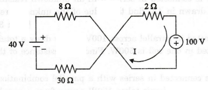
26.
Assuming the internal resistance of the batteries to be zero, calculate the
current supplied by the two batteries in the network shown in figure.
[Ans: I1 = -1A, I2 = 5
A]
27.
Find the current in the load resistor of the circuit in figure.
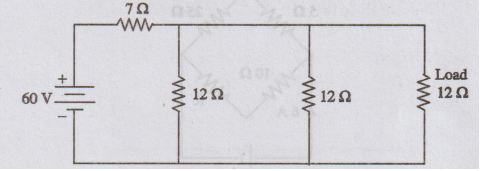
[Ans: 1.818 A]
28.
For the circuit in figure, find the load current and power.
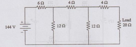
[Ans: 2A, 80W]
29.
In the network shown in figure, find the magnitude and direction of each branch
A current by mesh current method.
[Ans:
I1 = 1.886 A; I2 = 0.341 A]
30.
Calculate the current in each branch of the circuit shown in figure.
[Ans: I1 = 1.65 A, I2 =
2.16 A; I3 = 1.5 A]
31.
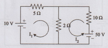
Determine the current in the 4 2 branch in the circuit shown in figure.
[Ans: 4.11 A]
32.
Determine mesh currents I1 and I2 for the given circuit shown in figure.
[Ans:
I1 = 0.25 A, I2 = 4.125 A]
33.
Determine the mesh current I1 in the circuit shown in figure.
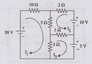
[Ans:
I1 = 3.3 A]
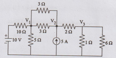
34.
Write the node voltage equations and determine the currents in each branch for
the network shown in figure.
[Ans:
V1 = 19.85 V, V2 = 10.9 V, I10 = 1.985 A I3
= 2.98 A, I5 = 2.18 A, I1 = 0.9 A]
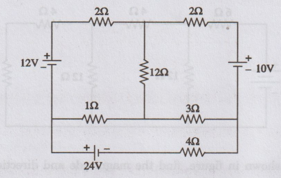
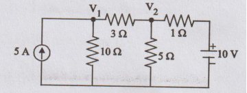
35.
Determine the voltages at each node for the circuit shown in figure.
[Ans: V1 = 8.06 V, V2 =
10.2 V, V3 = 3.07 V]
36.
Obtain the star connected equivalent for the delta connected circuit shown in
figure
[Ans: 4Ω,4.66 Ω, 4.31 Ω]
37.
Obtain delta-connected equivalent for the star-connected circuit shown in
figure.
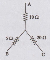
[Ans: 17.5Ω, 35 Ω, 70Ω]
Electric Circuit Analysis: Chapter - 1: Basic Circuit Analysis - DC : Tag: : Basic Circuit Analysis - DC | Electric Circuit Analysis - Unsolved Problems with Answer