Basic Civil & Mechanical Engineering: UNIT V: a. Refrigeration
Vapour compression refrigeration
Working Principal, Description, Layout Diagram, Uses
In the Vapour Compression Refrigeration System, Freon-12 or Freon-22 is used as the Refrigerant. A Compressor does work on the refrigerant vapour to increase its pressure and temperature.
VAPOUR COMPRESSION
REFRIGERATION
Principle
In the Vapour Compression Refrigeration
System, Freon-12 or Freon-22 is used as the Refrigerant. A Compressor does work
on the refrigerant vapour to increase its pressure and temperature.
The
refrigerant is circulated through the system. It alternately undergoes a change
of phase from vapour to liquid and again liquid to vapour during the cycle. The
latent heat of vaporization is used for absorbing the heat at low temperature
from the refrigerated space. A constant temperature can be maintained in this
space.
Description
See
Fig. 1. Vapour Compression Refrigeration System consists of the following
parts:
1.
Condenser
2.
Receiver
3.
Expansion Valve (Capillary Tube)
4. Evaporator
5.
Compressor
1. Condenser
The
delivery side of the Compressor is connected to a Condenser. Air or water is
used as the cooling medium in the condenser. Air is used for refrigerators and
window air conditioners. Water is used for large centralized air conditioning
systems.
2. Receiver
Receiver
is a vessel used to store the condensed liquid refrigerant coming from the
condenser.
3. Expansion Valve (Capillary Tube)
The
Receiver is connected to an Expansion Valve. The pressure of the liquid passing
through the expansion valve drops for reuse in the evaporator. Low capacity
systems like Refrigerators, Window air conditioners, etc., use a Capillary Tube
as an expansion valve. Solenoid valve is used as expansion valve in large
capacity systems.
4. Evaporator
An
Evaporator consists of coiled tubes. The substance to be cooled is placed in the
evaporator. It is the coldest region or space in the refrigerator and serves as
the Refrigerated Space or Freezer Compartment.
5. Compressor
The evaporator tube is connected to the
suction side of the Compressor. The compressor is driven by an electric motor.
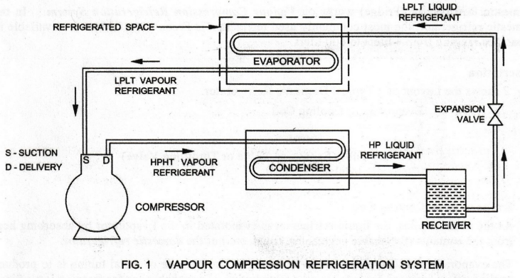
Working
The refrigeration effect is produced at the
Evaporator. The refrigerant enters the Evaporator at Low Pressure Low
Temperature (LPLT).
The
LPLT Liquid Refrigerant is evaporated and changed into vapour refrigerant at
the Evaporator. Here, the refrigerant absorbs its latent heat of vapourization
from the substances kept around the evaporator, thus cooling them at the
Refrigerated Space.
The
LPLT Vapour Refrigerant from the Evaporator is drawn by the suction side of the
Compressor. It is compressed to High Pressure High Temperature (HPHT) and
discharged to the Condenser through the delivery side of the Compressor.
Electric Power is supplied to the motor to run the compressor. Note that power
consumption is the major operating cost of the system.
In the Condenser, the latent heat of the
refrigerant is removed by circulating either atmospheric air or water. Thus,
the HPHT Vapour Refrigerant is cooled and condensed into liquid form.
The
High Pressure (HP) Liquid Refrigerant from the Condenser is collected in the
Receiver. The High Pressure Refrigerant passes through an Expansion Valve and
expands to Low Pressure. The Expansion Valve is a Capillary Tube in small
(domestic) refrigerators. The function of the Capillary Tube is to throttle the
refrigerant to Low Pressure Low Temperature. This LPLT Vapour Refrigerant
enters the Evaporator. The cycle is repeated.
Thermostat Switch:
The required low temperature is maintained in the refrigerator by a Thermostat.
The Thermostat is used to switch ON or OFF the compressor motor by a relay.
Uses:
Vapour Compression is used in domestic refrigerators, water coolers, air System
conditioners, etc.
Basic Civil & Mechanical Engineering: UNIT V: a. Refrigeration : Tag: : Working Principal, Description, Layout Diagram, Uses - Vapour compression refrigeration
Related Topics
Related Subjects

Basic Civil and Mechanical Engineering
BE3255 2nd Semester 2021 Regulation | 2nd Semester EEE Dept 2021 Regulation