Transmission and Distribution: Unit III: (b) Insulators
Voltage Distribution Over a String of Suspension Insulators
Consider a string of suspension insulators. The number of porcelain discs are connected in series with the help of metal links.
Voltage Distribution Over
a String of Suspension Insulators
Consider a string of suspension
insulators. The number of porcelain discs are connected in series with the help
of metal links. The Fig. 5.4.1 shows string of 4 porcelain disc suspension
insulators.
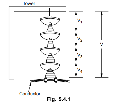
The porcelain portion which is an
insulator is in between the two metal fittings. Thus it forms a capacitor. This
is called "self capacitance" or "mutual capacitance". Hence
the whole string shown in the Fig. 5.4.1 will consist of 4 such self capacitors
in series. If only such self or mutual capacitors exist alone in series, the
voltage across them would have been equal and series charging current through
them would have been same.
But in addition capacitances, there
capacitance between fitting and the earth i.e. tower. The air acts as a
dielectric. Such a capacitance is called "shunt capacitance".
Due to shunt capacitors, the charging
current no longer remains same.
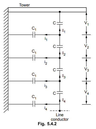
The different currents, mutual
capacitors and shunt capacitors are shown in the Fig. 5.4.2. The mutual
capacitors are denoted as C while the shunt capacitors are denoted as C1
Assuming the design of each section of the string same, the mutual capacitors
are assumed equal. Similarly all shunt capacitors are also assumed equal.
There will be capacitance between metal
fittings and the line conductor also. But its value is very small and generally
it is neglected.
The currents I1, I2,
I3, and I4 are charging currents
flowing through mutual capacitors while i1, i2, i3,
and i4 are the currents flowing through the shunt capacitors.
Due to the different charging currents,
each capacitor will get charged to different potential. Hence the voltage
across each section of the string will be different It is shown as V1,
V2, V3 and V4 in the Fig. 5.4.2.
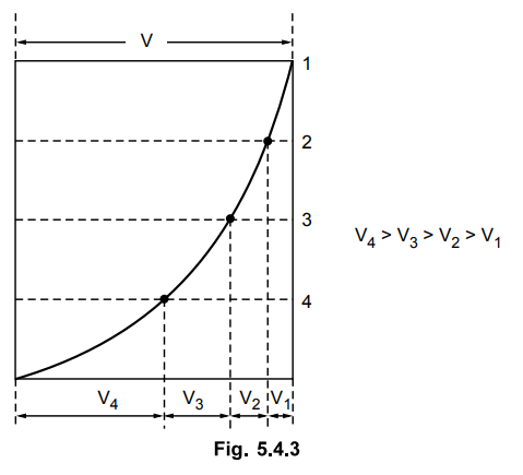
As the charging current is highest
nearest to the line conductor, the voltage across the capacitor nearest to the
line conductor will be maximum. Thus V4 will be maximum, for the
case considered. Hence the insulator adjacent to the line conductor is under
maximum electrical stress and is liable to puncture. The graphically such
potential variation can be shown as in the Fig. 5.4.3.
The following observations can be made
related to the voltage distribution over a string of suspension insulators :
1. The voltage distribution is not
uniform due to shunt capacitors.
2. The charging currents through various
mutual capacitors are different.
3. The voltage across the top unit
farthest from the line conductor is lowest.
4. The voltage across the bottom unit
which is adjacent to the line conductor is maximum.
5. Due to maximum voltage impressed on
the insulator nearest to the line conductor, it is under maximum electrical
stress.
6. Due to maximum electrical stress, the
insulator nearest to the line conductor is likely to puncture. Hence
practically the efforts are made to have uniform voltage distribution as far as
possible.
7. In case of d.c. voltage, the
capacitors do not play any role and the voltage distribution is obviously
uniform.
Review Question
1. Why the voltage distribution across the units of a string
insulator is not uniform ?
Transmission and Distribution: Unit III: (b) Insulators : Tag: : - Voltage Distribution Over a String of Suspension Insulators
Related Topics
Related Subjects

Transmission and Distribution
EE3401 TD 4th Semester EEE Dept | 2021 Regulation | 4th Semester EEE Dept 2021 Regulation