Linear Integrated Circuits: Unit V: Application ICs
Voltage Follower Regulator using Op-amp
Operating working principle, Functional Circuit Diagram
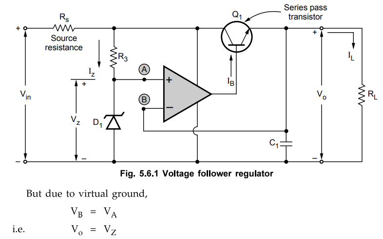
The voltage follower d.c. regulator is nothing but fixed voltage series regulator using op-amp. It is shown in the Fig. 5.5.1.
Voltage Follower Regulator using Op-amp
The
voltage follower d.c. regulator is nothing but fixed voltage series regulator
using op-amp. It is shown in the Fig. 5.5.1.
The
op-amp is used as a comparator. The supply of op-amp is derived from input
supply terminals. Hence op-amp supply voltages are +Vin and ground.
The inverting terminal of op-amp is connected to the output terminal.
VB
= Vo
While
the voltage of noninverting terminal i.e. node A is zener voltage Vz, decided
by the zener diode D1.
VA
= VZ
Key
Point Thus the output voltage is constant equal to
zener voltage.
The
series pass transistor is to supply the additional load current which op-amp
can not supply. For large load current, op-amp has to supply only base current
of the transistor, IB.
If
load current is less than 25 mA, series pass transistor Q1 does not
play any role and op-amp behaves as a voltage follower.
The
C1 is large capacitor of the order of 50 to 100 µF. The functions of
C1 are,
1.
To help to supply fast demands on regulator.
2.
To eliminate the possibility of any oscillatory behaviour of the regulator.
The
op-amp 741 can be used for the circuit. The heat sink must be provided to
series pass transistor. The minimum VCE required to keep Q1
operating is about 3 V. If it is below 3 V, the ripple content in the output
increases which affects the values of line and load regulations badly.
Review Question
1. Explain the working of series voltage regulator using op-amp.
Dec.-10, May-15,18 Marks 8
Linear Integrated Circuits: Unit V: Application ICs : Tag: : Operating working principle, Functional Circuit Diagram - Voltage Follower Regulator using Op-amp
Related Topics
Related Subjects

Linear Integrated Circuits
EE3402 Lic Operational Amplifiers 4th Semester EEE Dept | 2021 Regulation | 4th Semester EEE Dept 2021 Regulation