Electrical Machines: Unit IV: Single Phase Transformer
Voltage Regulation of Single Phase Transformer
• This decrease in the secondary terminal voltage expressed as a fraction of the no load secondary terminal voltage is called regulation of a transformer.
Voltage Regulation of Transformer
AU: May-06,07,09,14,17,19, Nov.-07, April-04, Dec.-07,10,11,17,18
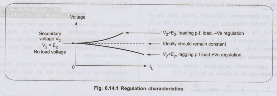
• Because of the voltage drop across the primary and secondary impedances it is observed that the secondary terminal voltage drops from its no load value (E2) to load value (V2) as load and load current increases.
• This decrease in the secondary terminal voltage expressed as a fraction of the no load secondary terminal voltage is called regulation of a transformer.
Let E2 = Secondary terminal voltage on no load
V2 = Secondary terminal voltage on given load
• Then mathematically voltage regulation at given load can be expressed as,
voltage regulation = E2-V2 / V2 × 100
• The ratio (E2 - V2 / V2) is called per unit regulation.
• The secondary terminal voltage does not depend only on the magnitude of the load current but also on the nature of the power factor of the load. If V2 is determined for full load and specified power factor condition the regulation is called full load regulation.
• As load current I1 increases, the voltage drops tend to increase and V2 drops more and more. In case of lagging power factor V2 < E2 and we get positive voltage regulation, while for leading power factor E2 < V2 and we get negative voltage regulation. This is shown in the Fig. 6.2.1.
Key Point: The voltage drop should be as small as possible hence less the regulation better is the performance of a transformer.
1. Expression for Voltage Regulation
• Mathematically percentage voltage regulation is defined as,
% R = E2-V2 /V2 × 100 = Total voltage drop / V2 × 100
• The total voltage drop depends on the nature of the power factor of the load.
osol navig no sestlov lenim
Case I : Lagging power factor load
• It is known that when the transformer is loaded, there are voltage drops across resistance and inductance. Hence the no load voltage E2 is given by,
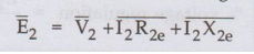
• For lagging p.f. load, I2 lags V2 by ϕ2. Take V2 as a reference phasor. The drop I2 R2e is in the direction of I2 while I2 X2e is at 90° to I2 R2e such that I2 lags by 90°.
• The phasor diagram is shown in the Fig. 6.14.2.
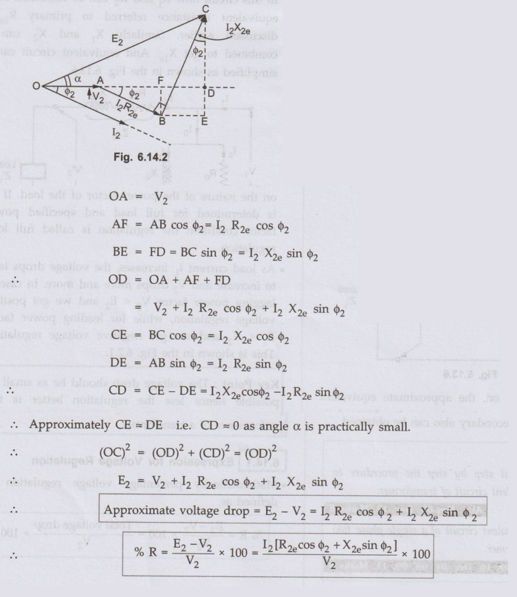
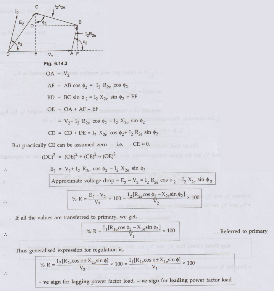
Case II: Leading power factor load
• The current I2 leads V2 by ϕ2 and the phasor diagram is as shown in the Fig. 6.14.3.
Key Point: If I2 or I1 in above expression is full load current it gives full load regulation.
2. Per Unit Representation
• From the regulation expression we can define constants of a transformer.

• The terms VR and Vx are called constants of a transformer because for the rated output I2, E2, R1e X1e ,R2e ,X2e are constants. The regulation can be expressed interms of VR and Vx as,
On no load condition, E2 = V2 and E1 = V1
• where V1 and V2 are the given voltage ratings of a transformer. Hence VR and Vx can be expressed as,
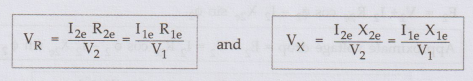
• where V1 and V2 are no load primary and secondary voltages.
• VR and Vx can be represented on percentage basis as,
Percentage resistive drop = VR × 100
Percentage reactive drop = Vx × 100
Key Point : Note that VR and Vx are also called per unit resistance and reactance respectively.
• Thus the % resistance and % reactance values of transformer winding on full load are,
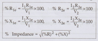
Key Point: The currents used must be full load currents to calculate % values of resistances and reactances of the transformer windings.
3. Zero Voltage Regulation
• We have seen that for lagging power factor and unity power factor condition V2 < E2 and we get positive regulation. But as load becomes capacitive, V2 starts increasing as load increases. At a certain leading power factor we get E2 = V2 and the regulation becomes zero. If the load is increased further, E2 becomes less than V2 and we get negative regulation.
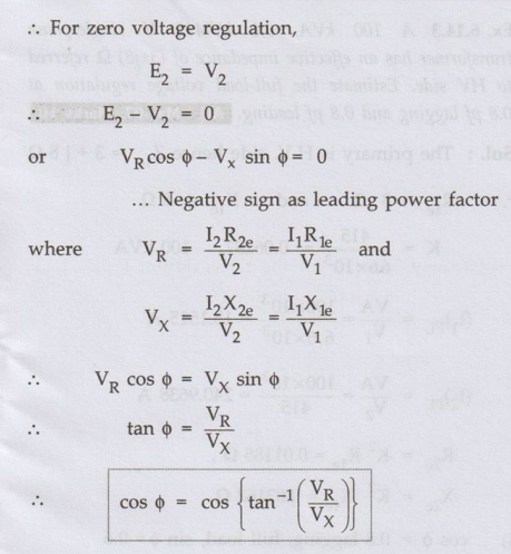
This is the leading p.f. at which voltage regulation becomes zero while supplying the load.
4. Condition for Maximum Voltage Regulation
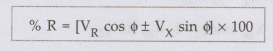
The per unit voltage regulation is,
% R = [VR cos ϕ + Vx sin ϕ] × 100
Findϕ for maximum voltage regulation by differentiating above equation with respect to ϕ,
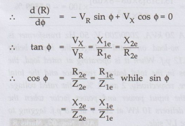
As tan is ϕ positive, maximum regulation occurs at lagging power factor. The magnitude of maximum regulation is,

Maximum regulation
Key Point: Thus the maximum regulation is equal to the per unit value of the equivalent impedance of the transformer.
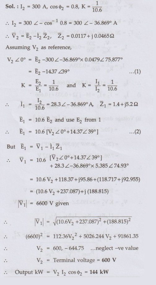
Ex. 6.14.1 A single phase transformer has Z1=1.4+j 5.2 Ω and Z2 = 0.0117+j0.0465 'Ω. The input voltage is 6600 V and the turn ratio is 10.6: 1. The secondary feeds a load which draws 300 A at 0.8 power factor lagging. Find the secondary terminal voltage and the kW output. Neglect no-load current. AU Dec.-18, Marks 10 + 3
Sol.:
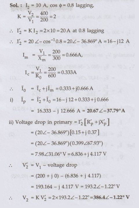
Ex. 6.14.2 The parameters of approximate equivalent circuit of a 4 kVA, 200/400 V, 50 Hz, ϕ transformer are: R'p=0.15 ; X'p=0.37 W; R0 = 600 Ω; Xm =300 Ω. When a rated voltage of 200 V is applied to the primary, a current of 10 A at lagging power factor of 0.8 flows in the secondary winding. Calculate
1) The current in the primary Ip.
2) The terminal voltage at the secondary side.
AU May-06, 09, 14, 17, Marks 8
Sol.:
Ex. 6.14.3 A 100 kVA, 6.6 kV/415 V single-phase transformer has an effective impedance of (3+j8)Ω referred to HV side. Estimate the full-load voltage regulation at 0.8 pf lagging and 0.8 pf leading. AU: May-07, Marks 10
Sol.:

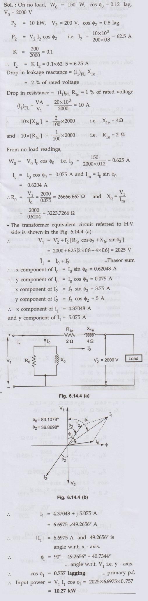
Ex. 6.14.4 A 20 kVA, 2000/ 200 V, 50 Hz transformer is operated at no-load on rated voltage, the input being 150 W at 0.12 p.f. When it is operating at rated load, the voltage drops in the total leakage reactance and the total resistance are, respectively, 2 and 1 % of the rated voltage. Determine the input power and power factor when the transformer delivers 10 kW at 200 V at 0.8 p.f. lagging to a load on the LV side. AU: Nov.-07, Marks 8
Sol. :
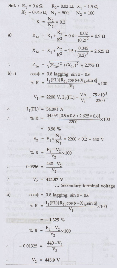
Ex. 6.14.5 A 75 kVA transformer has 500 turns primary and 100 turns secondary. The primary and secondary resistances are 0.4 Ω and 0.02 Ω respectively and the corresponding leakage reactances are 1.5 Ω and 0.045 Ω respectively. The supply voltage is 2200 V. Calculate a) Equivalent impedance referred to the primary circuit and b) The voltage regulation and secondary terminal voltage for full load at power factor of i) 0.8 lagging and ii) 0.8 leading. AU: Dec.-17, Marks 15
Sol. :
Ex 6.14.6 A single phase transformer on full load has an impedance drop of 20 V and resistance drop of 10 V. Calculate the value of power factor when its regulation will be zero. AU :April-04, Marks 6
Sol. :

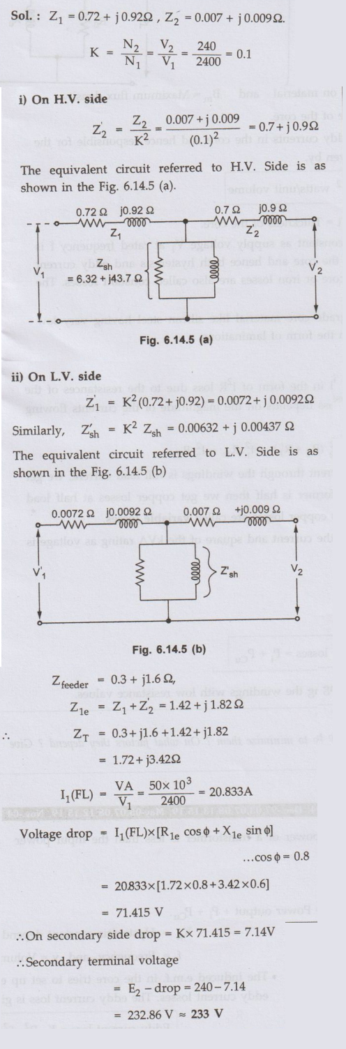
Ex. 6.14.7 A 50 kVA 2400: 240 V 60 Hz distribution transformer has a leakage impedance of 0.72+ j0.92Ω the high-voltage winding and 0.0070+ j0.0090'Ω in the low-voltage winding. At rated voltage and frequency, the impedance of the shunt branch accounting for the exciting current is 6.32+ j43.7Ω when viewed from the low-voltage side. Draw the equivalent circuit referred to
i) The high-voltage side and
ii) The low-voltage side and label the impdance numerically. The transformer is used to step down the voltage at the load end of a feeder whose impedance is 0.30+ j1.60Ω. The voltage at the sending end of the feeder is 2400 V. Find the voltage at the secondary terminals of the transformer when the load connected to its secondary terminals draws rated current from the transformer and the power factor of the load is 0.80 lagging. Neglect the voltage drops in the transformer and feeder caused by the exciting current. AU May-19, Marks 13
Sol. :
Review Questions
1. Explain the causes of voltage drops in a power transformer. AU: Dec.-11, Marks 4
2. Derive an expression for the approximate voltage drop in a loaded transformer.
3. Explain the term percentage impedance as applicable to transformer. AU: Dec.-07, Marks 4
4. Define voltage regulation of a two winding transformer and explain its significance. AU: Dec.-10, Marks 4
5. Derive the condition for zero voltage regulation.
6. Derive the condition for maximum voltage regulation.
7. A 200 kVA, 2200 V / 440 V, 50 Hz, single phase transformer is operating at full load, 0.8 lagging p.f. condition. The voltage on the secondary of the transformer at full load, 0.8 lagging p.f. condition is 400 V. Calculate the voltage regulation of the transformer for the above mentioned condition. Also calculate load supplied in kW. [Ans. 10%, 145.45 kW]
Electrical Machines: Unit IV: Single Phase Transformer : Tag: : - Voltage Regulation of Single Phase Transformer
Related Topics
Related Subjects

Electrical Machines I
EE3303 EM 1 3rd Semester EEE Dept | 2021 Regulation | 3rd Semester EEE Dept 2021 Regulation