Linear Integrated Circuits: Unit V: Application ICs
Voltage Regulator Characteristics
Operating working principle, Features, Functional Block Diagram, Performance factors
A power supply is an important element of any type of electronic circuit. It provides the supply for the proper operation of the circuit. The successful operation of the circuit depends on the proper functioning of the power supply.
Introduction to Voltage Regulator
A
power supply is an important element of any type of electronic circuit. It
provides the supply for the proper operation of the circuit. The successful
operation of the circuit depends on the proper functioning of the power supply.
Most of the electronic circuits require a smooth d.c. voltage as that of
batteries. The power supply in a circuit tries to provide such a constant
voltage. A block diagram containing the parts of a typical power supply and
nature of the voltages at various points is shown in the Fig. 5.2.1.
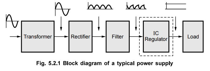
The
a.c. voltage is connected to a transformer. The transformer steps down the a.c.
voltage down to the level required for the desired d.c. output. The rectifier
converts a.c. voltage to a d.c. voltage. The filter circuit is used after the
rectifier to reduce the ripple content in the d.c., to make it smoother. Still
then the d.c. voltage usually has some ripple or a.c. voltage variation. This
voltage is called unregulated d.c. voltage. A regulator circuit is a circuit
used after the filter, which not only makes the d.c. voltage smooth and almost
ripple free but also keeps the d.c. output voltage constant though input d.c.
voltage varies under certain conditions. It keeps the output d.c. voltage
constant under the variable load conditions, as well. Thus input to a regulator
is an unregulated d.c. voltage while the output of a regulator is a regulated
d.c. voltage, to which the load is connected. Such a regulator block is shown
dotted in the Fig. 5.2.1. Now a days, complete regulator circuits are available
in integrated circuit form.
Review Question
1. Draw and explain the block diagram of a typical power supply.
Voltage Regulator Characteristics
Let
us study some important regulator characteristics and the factors affecting the
load voltage.
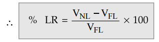
1. Load Regulation
The
load regulation is the change in the regulated output voltage when the load current
is changed from minimum (no load) to maximum (full load).
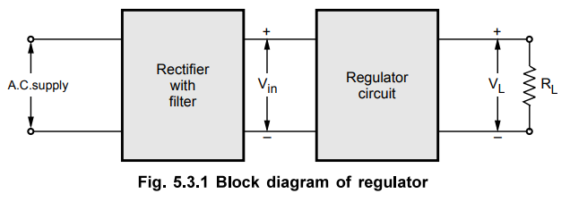
Consider
the block diagram of regulator circuit shown in the Fig. 5.3.1.
The
load regulation is denoted as LR and mathematically expressed as,
LR
= VNL – VFL
where
VNL = Load voltage with no load current.
VFL
= Load voltage with no load current.
The
load regulation is often expressed as percentage by dividing the LR by full
load voltage and multiplying result by 100.
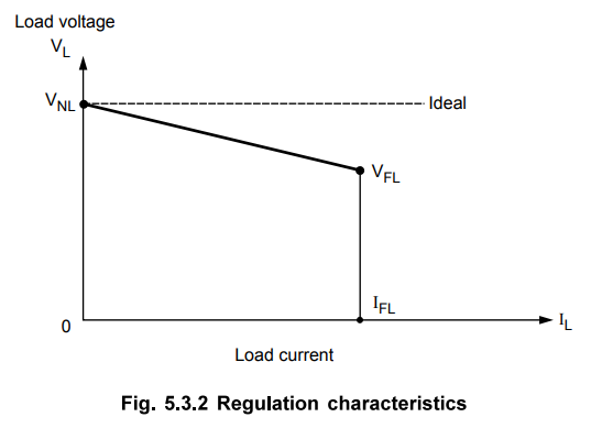
The
graph of load current against load voltage is called regulation characteristics
of a power supply. The ideal value of load regulation is zero. Less the
regulation, better is the performance of regulator. The regulation
characteristics is shown in the Fig. 5.3.2.
2. Source Regulation/Line Regulation
The
input to the unregulated power supply i.e. rectifier circuit is 230 V a.c.
supply. This line voltage may change, under the different load conditions. This
affects the output voltage of rectifier which is Vin for a regulator
circuit. Hence the characteristics which gives source effect on regulator
performance is defined.
The
source regulation is also called line regulation or source effect and denoted
as SR.
The
SR is defined as the change in the regulated load voltage for a specified range
of line voltage, typically 230 V ± 10 %.
Mathematically
it is expressed as,
SR
= VHL - VLL
where
VHL = Load voltage with no load current.
VLL
= Load voltage with no load current.
The
percentage source regulation is defined as,
%
SR = SR / Vnom × 100
where
Vnom - Nominal load voltage
3. Output Impedance
The
output impedance of regulated power supply is very small. It can supply
different loads keeping load voltage constant. In a series regulator, the pass
transistor Q2 is an emitter follower which has very low output
impedance Zout. The use of voltage feedback reduces it to,
Zout
(CL) = Zout / 1 + AB, A = Forward gain, B = Feedback factor
Hence
regulated power supply has output impedance in milliohms so it is very stiff
voltage source.
4. Ripple Rejection
The
output of rectifier and filter circuit consists of ripples. The ripple is equivalent
to periodic changes in input voltage. Due to the negative feedback, the ripple
voltage gets attenuated by large amount. The factor by which it gets reduced is
1+AB. Mathematically the output ripple of a voltage regulator is given by,
VR(out)
= VR(in) / 1 + AB
The
performance parameter ripple rejection denoted as RR is defined as,
RR
= VR(out) / VR(in)
In
datasheet, it is expressed in decibels (dB)
RR'
= 20 log RR = 20 log VR(out) / VR(in) dB
Key
Point As VR(out) is always less than
VR(in) RR’ i.e. RR in dB is always negative when difined as VR(out)
/ VR(in)
5. The Load Current (IL)
As
discussed, the load current affects the load voltage. The variation in load is
indicated by the variation in the load current. Ideally the output voltage
should remain constant for the variation of load from no load to the full load
condition.
6. Temperature
The
rectifier using the components like diodes is temperature sensitive. Hence the
temperature is an important factor responsible for the changes in the load
voltage. The semiconductor devices used in power supplies, have their
characteristics which is temperature dependent.
The
voltage regulator circuit mainly, has to consider the above discussed factors
and has to provide constant d.c. load voltage irrespective of changes in load,
line voltage and the temperature.
Review Question
1. What are the various performance factors of a regulator ?
Define them.
Linear Integrated Circuits: Unit V: Application ICs : Tag: : Operating working principle, Features, Functional Block Diagram, Performance factors - Voltage Regulator Characteristics
Related Topics
Related Subjects

Linear Integrated Circuits
EE3402 Lic Operational Amplifiers 4th Semester EEE Dept | 2021 Regulation | 4th Semester EEE Dept 2021 Regulation