Linear Integrated Circuits: Unit III: Applications of Op-amp
Wien Bridge Oscillator using Op-amp
Working Principle, Circuit Diagram, Advantages, Design, Solved Example Problems | Operational amplifier
Generally in an oscillator, amplifier stage introduces 180° phase shift and feedback network introduces additional 180° phase shift, to obtain a phase shift of 3609 (2TI radians) around a loop. This is required condition for any oscillator.
Wien Bridge Oscillator
Generally
in an oscillator, amplifier stage introduces 180° phase shift and feedback
network introduces additional 180° phase shift, to obtain a phase shift of 3609
(2TI radians) around a loop. This is required condition for any oscillator. But
Wien bridge oscillator uses a noninverting amplifier and hence does not provide
any phase shift during amplifier stage. As total phase shift required is 0° or
2 nn radians, in Wien bridge type no phase shift is necessary through feedback.
Thus the total phase shift around a loop is 0°. Let us study the basic version
of the Wien bridge oscillator and its analysis.
A
basic Wien bridge used in this oscillator and an amplifier stage is shown in
the Fig. 3.18.1.
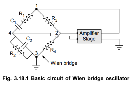
The
output of the amplifier is applied between the terminals 1 and 3, which is the
input to the feedback network. While Fig. 3.18.1 Basic circuit of Wien bridge
oscillator the amplifier input is supplied from the diagonal terminals 2 and 4,
which is the output from the feedback network. Thus amplifier supplied its own
input through the Wien bridge as a feedback network.
The
two arms of the bridge, namely R1 C1 in series and R2,
C2 in parallel are called frequency sensitive arms. This is because
the components of these two arms decide the frequency of the oscillator. Let us
find out the gain of the feedback network. As seen earlier input to the
feedback network is between is 1 and 3 while output Vf of the
feedback network is between 2 and 4. This is shown in the Fig. 3.18.2. Such a
feedback network is called lead-lag network. This is because at very low
frequencies it acts like a lead while at very high frequencies it acts like lag
network.
Now
from the Fig. 3.18.2, as shown,


This
is the frequency of the oscillator and it shows that the components of the
frequency sensitive arms are the deciding factors, for the frequency.
In
practice, R1 = R2 = R and C1 = C2 =
C are selected.

We
get the magnitude of the feedback network at the resonating frequency of the
oscillator as,

The
positive sign of β indicates that the phase shift by the feedback network is
0°. Now to satisfy the Barkhausen criterion for the sustained oscillations, we
can write,

Another
important advantage of the Wien bridge oscillator is that by varying the two
capacitor values simultaneously, by mounting them on the common shaft,
different frequency ranges can be provided.
1. Wien Bridge Oscillator using Op-amp
The
Fig. 3.18.4 shows the Wien bridge oscillator using an op-amp.

The
resistance R and capacitor C are the components of frequency sensitive arms of
the bridge. The resistance R and R1 form the part of the feedback
path. The gain of noninverting op-amp can be adjusted using the resistance R
and R1. The gain of op-amp is,
A
= 1 + Rf / R1
To satisfy Barkhausen criterion that Aβ ≥ 1 it is necessary that the gain of the noninverting op-amp amplifier must be minimum 3.
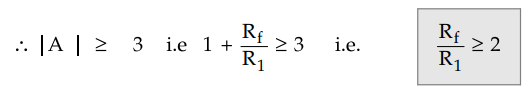
Thus
ratio of Rf and R1 must be greater than or equal to 2.
The
frequency of oscillations is given by,

The
feedback is given to the noninverting terminal of op-amp which ensures zero
phase shift. It is used popularly in laboratory signal generators.
If
in a Wien bridge feedback network, two resistances are not equal i.e. they are
R1 and R2 while two capacitors are not equal i.e. they
are C1 and C2 then the frequency of oscillations is given
by,

With
R1 = R2 = R and C1 = C2 = C we get
it as l/2π RC as stated earlier.
The
simplified circuit diagram of the Wien bridge oscillator is shown in the Fig.
3.18.5.

2. Advantages
The
various advantages of Wien bridge oscillator are,
1.
By varying the two capacitor values simultaneously, by mounting them on the
common shaft, different frequency ranges can be obtained.
2.
The perfect sine wave output is possible.
3. It is useful audio frequency range i.e. 20 Hz
to 100 kHz.
3. Wien Bridge Oscillators Design
Select
the capacitor value much larger than the stray capacitance, about 0.01 to 0.05
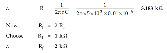
μF. From the equation of frequency, obtain the value of R.
R
= 1 / 2π fC
Then for noninverting amplifier,
Rf
= 2 R1
Choose
R1 and design the value of Rf. Keep Rf
variable for fine adjustments.
Example
3.18.1 Design the Wien bridge oscillator circuit to
have output frequency of 5 kHz.
May-18,
Marks 4
Solution
:
Choose C = 0.01 µF
Use
standard value of 2.2 k2 to have ACL > 3. The designed circuit is
shown in the Fig. 3.18.6.

Review Question
1. Draw the circuit of
a Wien bridge oscillator using op-amp and derive an expression for its
frequency of oscillation. May-04, Marks 8
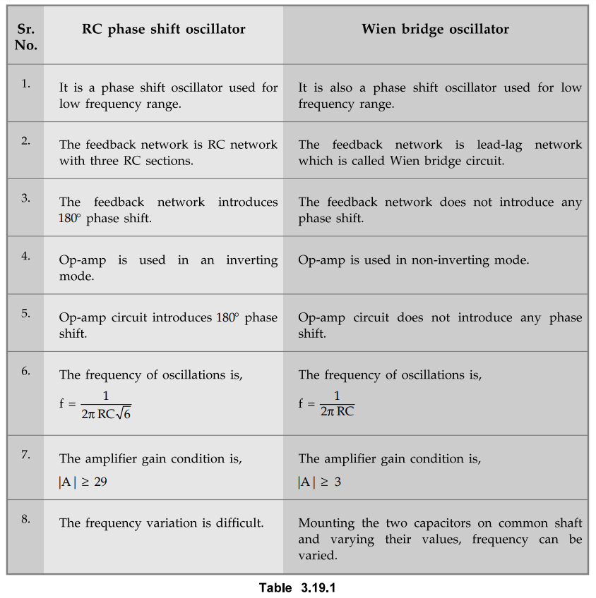
Comparison of RC Phase Shift and Wien Bridge Oscillators
The
similarities and the difference between the two oscillators are given in the
table 3.19.1
Linear Integrated Circuits: Unit III: Applications of Op-amp : Tag: : Working Principle, Circuit Diagram, Advantages, Design, Solved Example Problems | Operational amplifier - Wien Bridge Oscillator using Op-amp
Related Topics
Related Subjects

Linear Integrated Circuits
EE3402 Lic Operational Amplifiers 4th Semester EEE Dept | 2021 Regulation | 4th Semester EEE Dept 2021 Regulation