Electrical Machines: Unit II: D.C. Generators
Winding Pitches
DC Generators
Now we will consider the definitions of different types of winding pitches, required in the design of the armature winding.
Winding
Pitches
•
Now we will consider the definitions of different types of winding pitches,
required in the design of the armature winding.
1. Back Pitch
•
The distance which is measured interms of armature conductors i.e. between top
and bottom coil sides of a coil measured around the back of the armature i.e.
away from the commutator is called back pitch and is denoted by yь.
It is measured interms of coil sides.
Key Point:
Since it is difference between odd and even number, it is always odd number.
•
The size of the coil is decided by the back pitch. The back pitch is normally
equal to coilsides per pole. It is shown for lap and wave type of winding in
the Fig. 3.5.1.
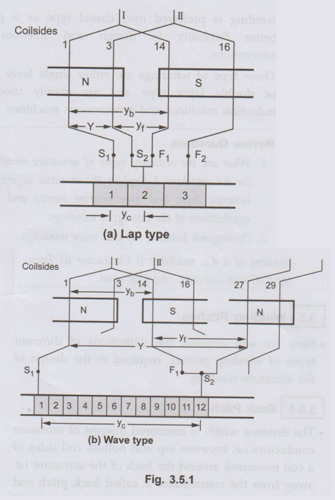
•
The back pitch for the winding shown in the Fig. 3.5.1 is yb 14 – 1
= 13 as coilsides 1 and 14 are of coil number I.
2. Front Pitch
• It is defined as the distance measured between two coilsides which are connected to same commutator segment. It denoted by Y. The front pitch for the winding shown in the Fig. 3.5.2 is Yf = 14 – 3 = 11.
This
is the front pitch for lap winding while for wave winding yf =
27-14= 13. The front pitch for both lap and wave type winding is odd. If for a
lap winding the connections are traced then the movement is backwards (coilside
14 to coilside 3). Hence the type of winding can be determined from front pitch
and it does not affect the size of coils.
3. Winding Pitch
•
It is defined as the distance between the starts of two consecutive coils
measured in terms of coilsides. It is denoted by Y.
For
Lap winding, Y = Yb-Yf
For
Wave winding, Y = Yb +Yf
•
For the lap winding shown in the Fig. 3.5.1 the winding pitch is Y = 13 - 11 =
2 while for wave winding Y = 13+ 13 = 26. It is also the distance round the
armature between two consecutive conductors. Practically, coil pitches or
winding pitches as low as eight tenths of a pole pitch are employed without
much reduction in e.m.f.
Key Point:
Fractional pitched windings are intentionally used so as to achieve saving in
copper of the end connections and for improvement in commutation.
4. Commutator Pitch
• It is defined as the distance between the two commutator segments to which the two ends i.e. starts and finish of a coil are connected. It is measured in terms of commutator segments and it is denoted by yc. For the windings shown in the Fig. 3.5.1.
Ус
= 2 – 1 = 1 for simplex lap winding
Yc
= 12 – 1 = 11 for simplex wave winding
•
For lap winding yc, is the difference between Yb and yf
while for wave winding yc, is the sum of Yb and yf.
The number of bars between the coil leads is commutator pitch. In general yc,
is the 'plex' of lap wound armature. It is 1, 2, 3 for simplex, duplex, triplex
lap windings respectively.
•
On tracing through simplex lap winding, a segment adjacent to the first one is
reached after traversing through one coil. For simplex wave winding, the
adjacent segment is reached after traversing through P/2 coils.
Review Question
1. Define and explain
back pitch, front pitch, commutator pitch winding pitcg for armature winding.
Electrical Machines: Unit II: D.C. Generators : Tag: : DC Generators - Winding Pitches
Related Topics
Related Subjects

Electrical Machines I
EE3303 EM 1 3rd Semester EEE Dept | 2021 Regulation | 3rd Semester EEE Dept 2021 Regulation