Electric Circuit Analysis: Unit V: Resonance and coupled circuits
Worked examples
Problems on parallel resonance circuits
Electric Circuit Analysis: Unit IV: Three phase circuits : Worked examples
WORKED EXAMPLES
ON PARALLEL RESONANCE CIRCUITS
Example
1 For the parallel network shown in figure, determine the value of R for
resonance.
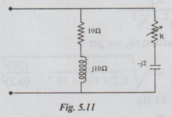
Solution:
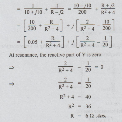
The total admittance Y = Y1 + Y2
Example
2 A coil of 20 Ω resistance has an inductance of
0.2 H and is connected in parallel with a condenser of 100 uF capacitance.
Calculate the frequency at which the circuit will act as a non-inductive
resistance of R ohms. Find also the value of R.
Solution: The circuit is given to be acting as non-inductive resistance.
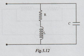
This
means that the circuit is at resonance.
The
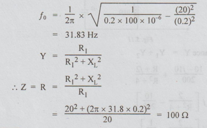
resonant frequency is given by
fo
= 1/2π × √1/LC – R12 / L2 … (i)
At
resonance, Y = R1 / R12 + XL2 ... (ii)
Substituting
the values in equation (i), we get
Example
3 Find the values of R, and Rc for the circuit in the following fig in order
that the circuit is to resonate at all frequencies. Derive the formula used.
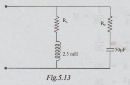
Solution:
For derivation, please refer parallel resonance case (c).
RL
= RC = √L/C = √2.5 × 10⁻³ / 50 × 10-6
=
7.07 Ω
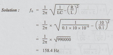
Example
4 Find resonant frequency of the circuit shown.
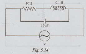
Solution:
Example
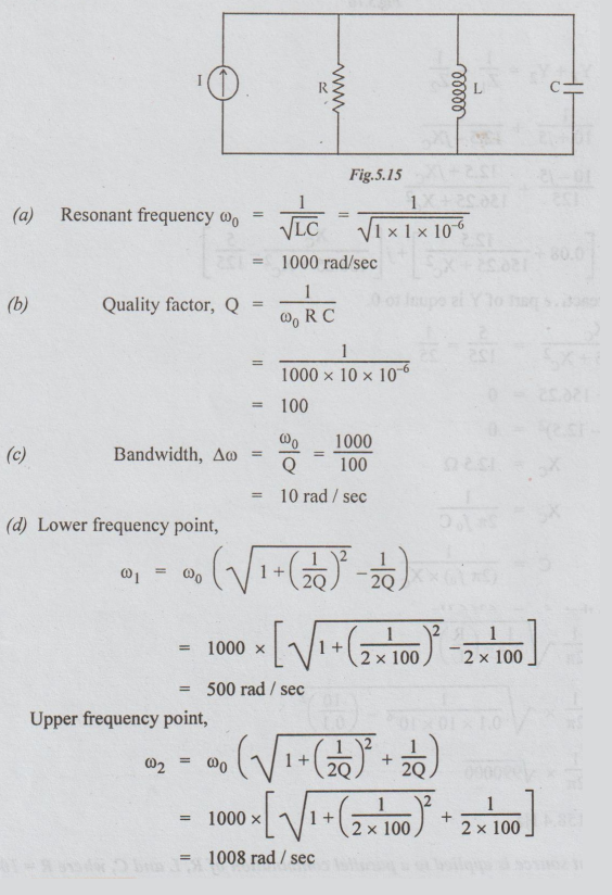
5 A current source is applied to a parallel combination of R, L and C, where R
= 10 ohms, L = 1H and C =1 μF.
(a)
Compute the resonant frequency.
(b)
Find the quality factor.
(c)
Calculate the value of the bandwidth.
(d)
Compute the lower and upper half frequency points of the bandwidth.
Solution:
Example
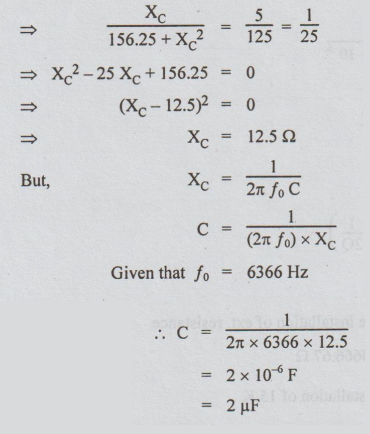
6 Determine the value of the capacitance C in order that the circuit in the
figure is resonant at 6366 Hz.
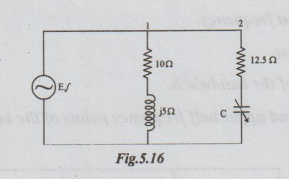
Solution:
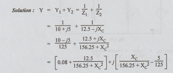
At
resonance, the reactie part of Y is equal to 0.
Electric Circuit Analysis: Unit V: Resonance and coupled circuits : Tag: : Problems on parallel resonance circuits - Worked examples
Related Topics
Related Subjects

Electric Circuit Analysis
EE3251 2nd Semester 2021 Regulation | 2nd Semester EEE Dept 2021 Regulation