Electric Circuit Analysis: Unit V: Resonance and coupled circuits
Worked examples
Coupled circuits
Electric Circuit Analysis: Unit V: Resonance and coupled circuits : Worked examples
WORKED EXAMPLES
Example
1 Two coupled coils with L1 = 0.02 H, L2 = 0.01 H and K =
0.5 are connected in four different ways, series aiding series opposing and
parallel with both arrangements of the winding sense. What are the four
equivalent inductances?
Solution:
M
= K√L1 L2
=
0.5 √0.02 × 0.01
=
7.07 × 10⁻³ H = 0.00707 H
(a) For a series aiding
Total
inductance = L1+ L2 + 2M
=
0.02 + 0.01 + 2 (0.00707)
=
0.044 H
(b)
For a series opposition
Total
inductance = L1 L2 – M2 / L1+ L2
– 2M
=
0.02 + 0.01-2(0.00707) = 0.016 H
(c)
For parallel aiding
Total
inductance
L1
L2 – M2 / L1+ L2 – 2M
=
0.02 × 0.01 - (0.00707)2 / 0.016
M
= 1.5 × 10⁻⁴ / 0.016 = 9.4 mH (milli Henrys)
(d)
For parallel opposition
Total
inductance = L1 L2
– M2 / L1+ L2 + 2M
=
1.5 × 10⁻⁴ / 0.044
=
3.41 milli Henrys
Example
2(a) What is the maximum possible mutual inductance of two inductively coupled coils
with self inductances
L1
L2 = 25 mH
L2
= 100 mH ?
Solution:
Mmax
= √ L1 L2 since K = 1 for maximum M
√25
× 100 = 50 milli Henrys
to
tort mod 2291 af (8E)
Example
2(b) Two inductors are connected as shown in fig. 5.34. What is the value of
the effective inductance of the combination?
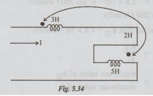
Solution:
Effective inductive L = L1 + L2 – 2M
=
3 + 5 – 2 × 2
=
4 H
[Note: As the current enters
the first coil at dotted terminal and leaves the other coil as dotted terminal,
M is taken as negative.]
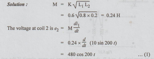
Example
3 Two coupled coils with respective self inductances L1 = 0.8 H and
L2 = 0.2H have a coupling coefficient of 0.6. Coil 2 has 500 turns.
If the current in coil 1 is i1 (t) = 10 sin 200 t, determine the voltage at
coil 2 and the maximum flux set up by the coil 1.
Solution:
Let
the flux in coil 2, due to a flux ϕ1 in coil 1 be ϕ12.
Then, e2 is also obtained in the following

=
0.96 /200 sin 200 t webers
=
4.8 × 10⁻³ x sin 200 t webers
ϕ12
is maximum when sin 200 t is unity.
The
maximum value of the flux ϕ12 = 4.8 × 10⁻³ webers
By
definition, K = ϕ12 / ϕ1
=
maximum value of ϕ12 / maximum value of ϕ1
maximum
value of ϕ1 = maximum value of ϕ12 / K
=
4.8 × 10⁻³ / 0.5.
=
9.6 × 10⁻³ webers
=
9.6 milli webers
Example
4 Show that the circuit shown in fig. 5.35 behaves with respect to terminals A
and B, as an open circuit or as a short circuit if
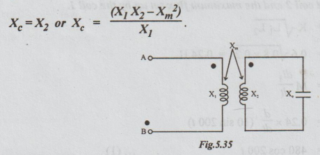
Solution:
With respect to terminals A and B, the network behaves as open circuit if the
net reactance between A and B (XAB) is infinite. The network behaves
like a short circuit if X Hence, first let us find out XAB. The
conductively coupled circuit of the given network is shown in fig. 5.36
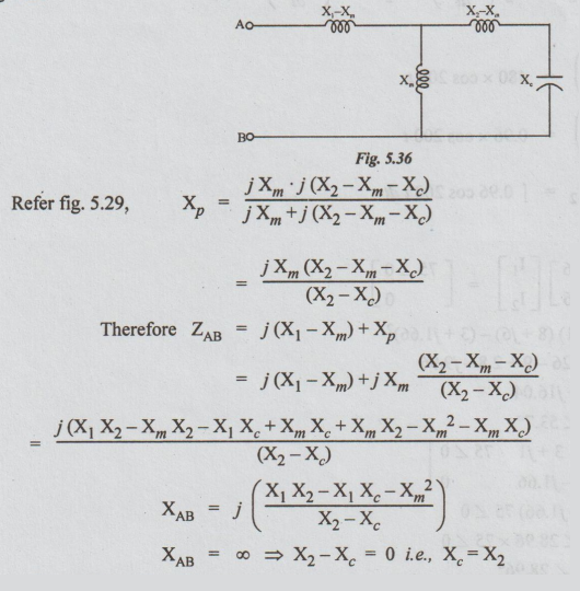
Hence,
when Xc = X2, the network with respect to terminals A and
B behaves like open circuit.

i.e.,
for this value of X, the network with respect to terminals A and B behaves like
a short circuit.
Example 5 In the coupled circuit shown in Fig.
5.37, find the voltage across the 5 ohm resistor.
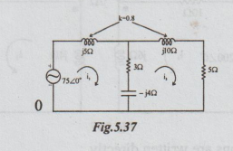
Solution:
Conductivity
coupled equivalent circuit is drawn as below for convenience.

Now by inspection,
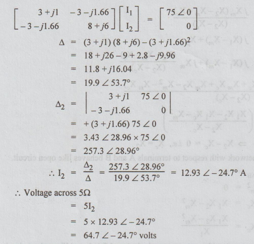
Example
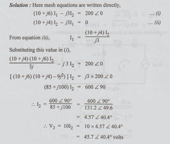
6 In the circuit find the phasor voltage V2

Solution:
Here mesh equations are written directly,
Electric Circuit Analysis: Unit V: Resonance and coupled circuits : Tag: : Coupled circuits - Worked examples
Related Topics
Related Subjects

Electric Circuit Analysis
EE3251 2nd Semester 2021 Regulation | 2nd Semester EEE Dept 2021 Regulation