Electric Circuit Analysis: Unit III: Transient Response Analysis
Solved Example Problems: DC Transients in RL, RC, RLC Circuit
Electric Circuit Analysis: Unit III: Transient Response Analysis : Worked examples - Transients in RL, RC, RLC Circuit
WORKED EXAMPLES
D.C. Transients in RL Circuit
Example 1 A d.c. voltage of 100 volts is applied to a series RL circuit with R = 252 What will be the current in the circuit at twice the time constant?
Solution: As the voltage source is in the circuit, the expression for rise in current is given by

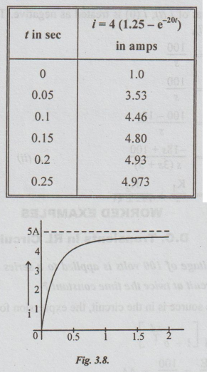
Example 2 Sketch the current given by i (t) = 5 - 4e-20t.
Solution:
i = 5 - 4e-20t
= 4 [ 1.25 - e-20t]
Let us assume that t take some values like t = 0, 0.1 sec, 0.15 sec, 0.2 sec, 0.25 sec. For these values of t, i is calculated and the result is tabulated for convenience.
The sketch is drawn in fig. 3.8.
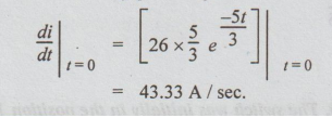
Example 3 In the circuit of the fig. 3.8, find the expression for the transient current and the initial rate of growth of the transient current.
p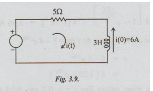
Solution: By applying KVL, we get
5i + 3 di / dt = 100 u (t) ... (i)
As i (0) is directed opposite to that of i (t), i (0) is treated as negative. That is i (0) = -6. Taking Laplace Transformation of equation (i),

Taking inverse Laplace Transformation, on both sides,
i (t) = 20 - 26 e-5t/ 3
To find the initial rate of growth of i.
Example 4 In the circuit shown in the fig. 3.9, switch S is in position 1 for a long time and brought to position 2 at time t = 0. Determine the circuit current.
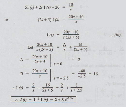
Solution: After closing the switch to the position 2 applying KVL, we get
5i + 2 di / dt = 10 ... (i)
Taking Laplace Transformation on both sides,
51 (s) + 2 {s I (s)- i (0+) } = 10 / s … (ii)
i (0+) is the current passing through the circuit just after the switch is at position 2. Since the inductor does not allow sudden changes in currents, this currents is equal to the steady state current when the switch was in position 1 [Because switch was in position 1 for long time.]
i (0+) = 50 / 5 = 10 A
Substituting this in equation (ii),
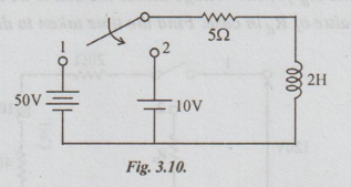
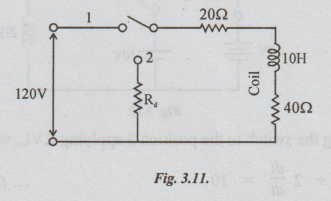
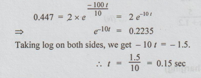
Example 5 In the circuit shown in fig. 3.10. The switch was initially in the position 1. (a) for Ra =500 Ω find the voltage across the coil the instant at which the switch is changed to position 2. (b) Calculate the value of the Ra for the voltage across the coil to be reduced to 120 V at the instant of switching. (c) with the value of Rain case. Find the time taken to dissipate 95% of stored energy.
Solution:
(a) Steady current with the switch in position 1 = 120 / 20 + 40 = 2A.
Now, with Rd = 500 and the switch changed to position 2, applying Kirchoff's voltage law, we get the following equation.
2 × 500 + 2 × 20 + voltage across the coil = 0 ... (i)
⇒ Voltage across the coil = - 1040 V
[-sign indicates that the voltage is in opposite direction.]
(b) In this case, the voltage across the coil = 120 V
Therefore, Rd × 2 + 2 × 20 -120 = 0
⇒ Rd = 80 / 2 = 40 Ω
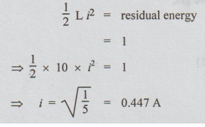
(c) Energy stored = 1/2 LI2
Energy stored = 1/2 × 10 × 22 = 20 joule
Given that, 95% of energy is dissipated. So, residual energy = 5% of energy stored = 0.05 × 20 = 1 joule.
Let i be the current at that instant. Then,
This case is a decay of current in R-L combination.
The equation for i is given by,
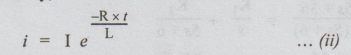
Here I = 2A, R = 40 + 40 + 20 = 100 Ω
L = 10 H
Substituting these values in (ii), we get,
Example 6 Find the current in the circuit shown in fig.3.12, at an instant t, after opening the switch if a current of 1 amp. had been passing through the circuit at the instant of opening.
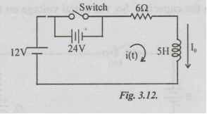
Solution:
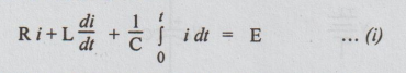
After t seconds of opening the switch, applying KVL, we get,
iR + L di / dt = E ... (i)
Here R = 6Ω, L = 5H, E = the total voltage of the circuit after opening the switch = 12 + 24 = 36V
Given that I0+ = Initial current = 1A
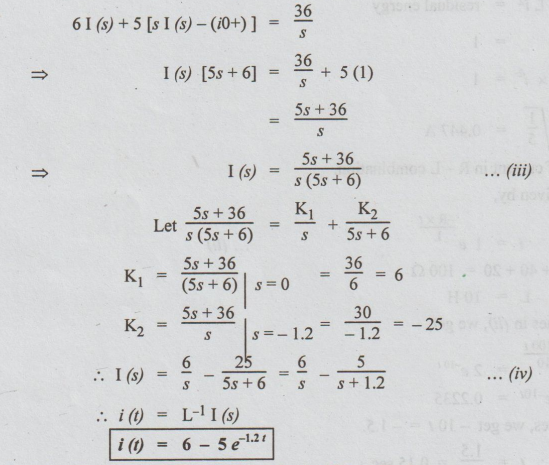
Putting the values of R, L and E in (i), we get,
6i + 5dt/dt = 36 …. (ii)
Taking Laplace transformation on both sides, we get,
WORKED EXAMPLES
D.C. Transients in RC Circuit
Example 7 A resistance R and a 2uF capacitor are connected in series across a 200V direct supply. Across the capacitor is a neon lamp that strikes at 120V. Calculate R to make the lamp strike 5 sec after the switch has been closed. If R = 5M 2, how long will it take the lamp to strike?
Solution: Case (i):

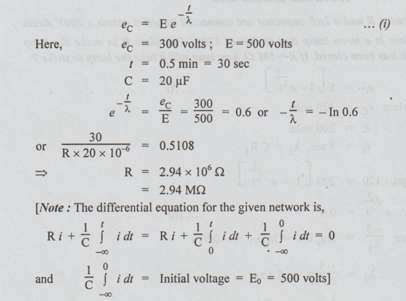
Example 8 A resistor is connected across the terminals of a 20 uF capacitor which has been previously charged to a.p.d. of 500V. If the p.d. falls to 300V in 0.5 min, calculate the resistance in megaohms.
Solution :
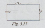
This is case of discharging of a capacitor.
The p.d. across C at any time t after the switch is closed is,
We can proceed to solve this equation by Laplace transform method. It yields the final solution which we already obtained.]
Example 9 Find how long it takes after the key is closed before the total current from the supply reaches 25 mA, when V = 10V, R1 = 500 2, R2 = 700 2 and C = 100 μF.
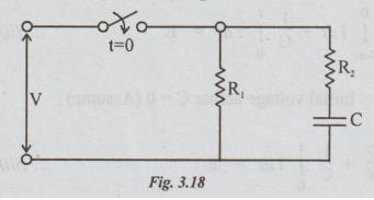
Solution:
Let i1 = the current through R1
i2 = current (charging current)
through the capacitor after t seconds of closing the switch.
I1 = V / R1 = 10 / 500 A = 20 mA
It is constant.
Given that Total current = i = 25 mA
By applying KCL,
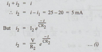
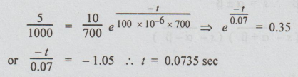
Substituting the known values in equation (i), we get
WORKED EXAMPLES
Transients in RLC Circuit
Example
10 A series RLC circuit has R = 502, L = 0.2 H and C = 50 μF. Constant voltage of
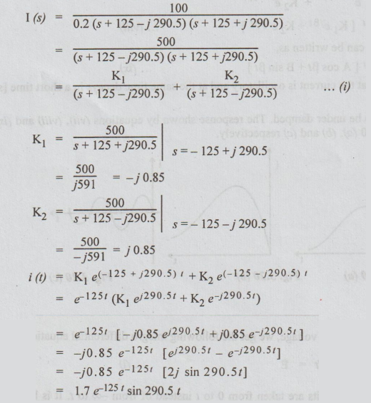
100V is impressed upon the circuit at t = 0. Find the expression for the
transient current assuming initially relaxed conditions.
Solution:
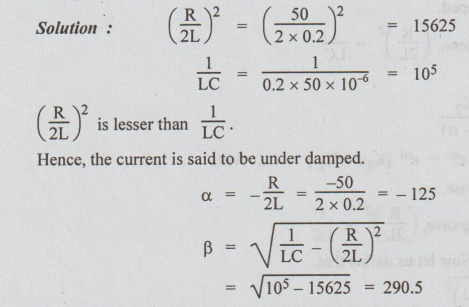
Hence,
the current is said to be under damped.
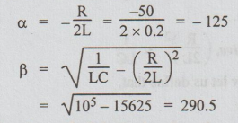
The
roots are a + jβ and a -jβ. Substituting the values of a and β, the roots are -
125 + j 290.5 and 125j 290.5.
Example
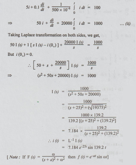
11 A series RLC circuit with R = 202, L = 10H, and C=5F has a constant voltage
V=100V applied at t=0. Find the current response in the circuit, assuming zero
initial condition.
Solution
:

Example
12 A series RLC circuit with R = 3002, L = 1H, and C = 100 x 10° F has a constant
voltage of 50V applied to it at t=0. Find the maximum value of current (assume
zero initial condition.)
Solution:
Let us solve this problem from the first principles.
After
t seconds of applying the voltage, we get the following integro differential
equation.
In
the above equation, the limits are taken from 0 to t instead of from co to t.
It is because, the initial voltage across the capacitor = V0
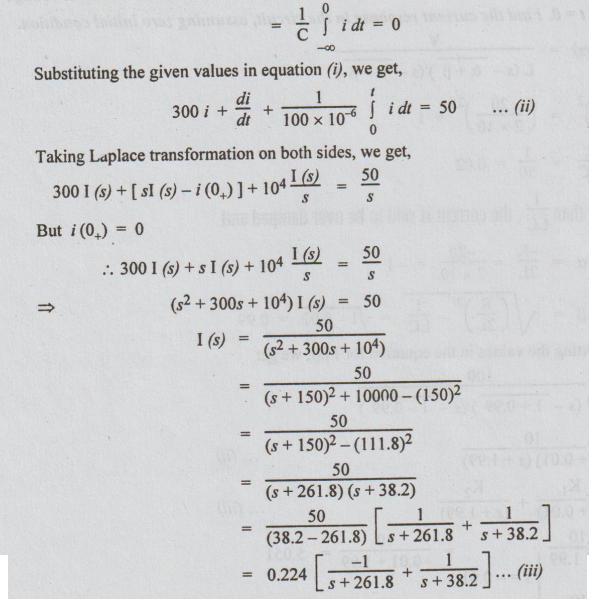
Taking
inverse Laplace of equation (iii), we get

It
is required to find the maximum value i(t)
Equating
di/dt to 0, we get the value of t. At this value of t, if d2i / dt2
is negative then i (t) is maximum.
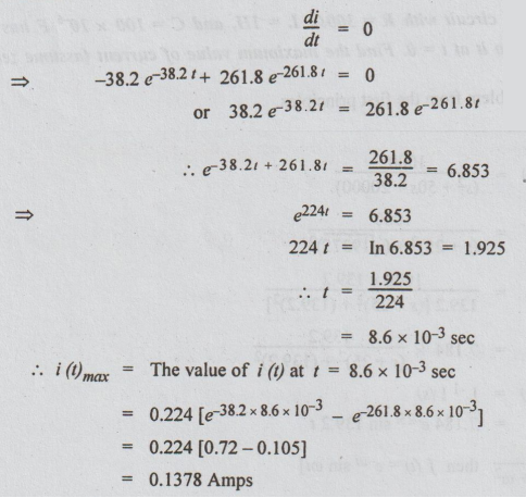
[Note: d2i / dt2
is not evaluated at t = 8.6 milli seconds. The student can find this
second derivative at t = 8.6 ms and may observe that it is negative.]
Example
13 A series RLC circuit with R = 52, L = 0.1 H and C = 500 x 106 F has a D.C.
voltage of 100V applied at t = 0 through a switch. Find the resulting current
transient.
Solution:
Let us solve this problem starting from the formation of integro differential
equation. It is obtained by applying KVL.
In
the above equation the initial voltage across the capacitor is assumed to be 0.
That is why the limits are 0 to t.
Substituting
the values given, we get,
Example
14 A step voltage V (t) = 100 u (t) is applied to a series R-L-C circuit with L
= 10 henrys, R = 2Ω, and C = 5 farads. The initial current in the circuit is
zero but there is an initial voltage of 50V on the capacitor in a direction
which opposes the applied source. Find the expression for the current in the
circuit.
Solution
:

Taking
Laplace Transform and substituting i (0) = 0.
[Note: Again if F (s) = ω / (s+a)2
+ ω2 then F (t) = et sin at formula is used. Instead we can solve
for i (t) by partial fractions.]
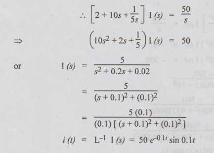
Example
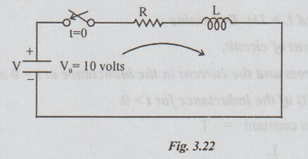
15 For a source-free RLC series circuit, the initial voltage across C is 10V
and the initial current through L is zero. If L = 20mH, C=0.5 μF and R = 100Ω,
evaluate i (1).
Solution:
Initial conditions given i (0+) = 0
V0
= q0 / C = 10
By
applying KVL, we get the following equation,
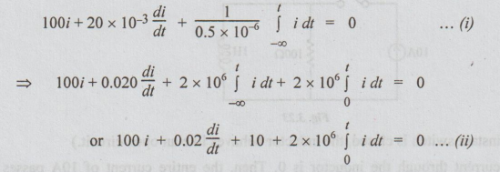
Taking
Laplace Transform on both sides,
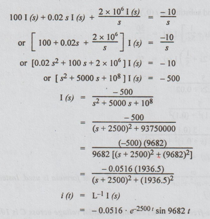
Example
16 A constant current source of 10A is suddenly applied at t=0 on R-L parallel
circuit with R = 100Ω and L = 1H. Determine:
(i)
the time constant of circuit,
(ii)
the voltage across and the current in the inductance at t = 0 and t → ∞, and
(iii)
the voltage V (t) of the inductance for t > 0.
Solution:
(i) Time constant = T
=
L/R
=
1/100
=
0.01 sec
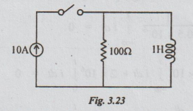
(ii) At t=0, (i.e., the instant switch is
closed, the inductor behaves like an open circuit.)
Hence,
at t = 0, the current through the inductor is 0. Then, the entire current of
10A passes through the resistor. The voltage across the resistor is equal to IR
= 10 × 100 = 1000V.
The
inductor is in parallel with the resistor. Hence, the voltage across it will
also be equal to 1000V.
At
t = ∞, the inductor behaves like a short circuit. Hence, the current through
the inductor becomes 10A. The current through the resistor reduces to 0. It
leads to voltage to be zero across both resistor and inductor.
(iii)
Let at any time t, i (t) be the current through the inductor. It is required to
find the expression for i (t) and hence voltage across the inductor.
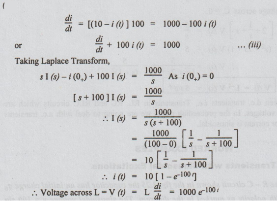
By
applying KCL, the current through the resistor = 10-i (t).
The
voltage across the inductor = L di/dt = 1 di/dt = di/dt … (i)
By
Ohms Law voltage across the resistor = [(10 - i (t)] × 100 ... (ii)
As
inductor and resistor are in parallel, voltage must be same, Hence, equating
equation (i) and (ii)
Example
17 For the circuit shown in fig. 3.24, find the voltage across the resistor 0.5Ω
when the switch, S, is opened at t = 0. Assume that there is no charge on the
capacitor and no current in the inductor before switching.
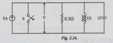
Solution:
[Note: For solving parallel circuits in transients, we have to apply KCL.
It yields the following equation.]

Till
now we have seen d.c. transients i.e., Transients in RL, RC and RLC circuits
which are energised by step input voltages. In the proceeding pages we are
going to deal with a.c. transients where the input voltage or current is
sinusoidal.
Electric Circuit Analysis: Unit III: Transient Response Analysis : Tag: : - Solved Example Problems: DC Transients in RL, RC, RLC Circuit
Related Topics
Related Subjects

Electric Circuit Analysis
EE3251 2nd Semester 2021 Regulation | 2nd Semester EEE Dept 2021 Regulation