Electric Circuit Analysis: Unit I: b. Basic circuits analysis
Worked Problems: AC circuits by nodal analysis method when ideal voltage source
ideal voltage source is connected between two nodes
Electric Circuit Analysis: Unit I: Basic circuits analysis : Worked Problems
WORKED
PROBLEMS
[Note: On
Nodal method when ideal voltage source is connected between two nodes]
Example
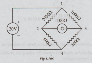
13 Find the current through the galvanometer in the circuit shown by nodal
method.
Solution:
In
this problem, the ideal voltage source is connected between two nodes. Take one
of these nodes as reference. Preferably, the node to which the negative
polarity of source is connected is taken as reference node. (say node 4). Then,
the voltage of the other node (i.e., node 1) = V1 = +20 volts.
Now
by applying Kirchoff's current law we can get the simultaneous equations and
find the node voltage. Finally, current can be found by applying ohm's law.
At
node 2:
V2
- V1 / 200 + V2 - V4/ 500 + V2 - V3 / 100 = 0
⇒ 5 (V2 - V1)
+ 2 (V2 - V4) + 10 (V2-V3) = 0
=>
5 (V2 - 20)+ 2 (V2-
0) + 10 (V2 - V3) =0
⇒ 17 V2 - 10
V3 = 100 ...(i)
Applying
KCL at node 3, we get
(V3
- V1) / 1000 + (V3 -
V2) / 100 + (V3 - V4)/ 200 = 0
⇒ (V3 - V1)
+ 10 (V3 - V2)+ 5 (V3 - V4) = 0
⇒
(V3-20) + 10 (V3 - V2) + 5 (V3-0) =
0
⇒ -10 V2 + 16
V3 = 20
⇒ -V2 + 1.6 V3 = 2
....(ii)
Adding (i) and (ii), we get
17.2
V3 =134
V3 =7.8 volts
V2
= 1.6 V3 - 2 = 1.6 (7.8) - 2
=12.48
- 2
=
10.48 volts
The
current through galvanometer = IG
=
V2 - V3 /100
=
10.48 - 7.8 / 100 = 0.0268 A
=
26.8 mA
[Note:
(i) In the above problem we can not write
matrix form, by inspection:
(ii) The student is advised to
check this answer by solving the problem by either branch current method or
mesh current method.
(iii) The same method is applicable
for A.C. circuits with ideal voltage source]
Example
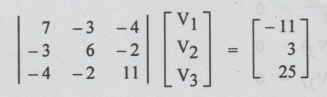
14 Draw a possible network having the following nodal equations and determine
the nodal voltages.
7V1
- 3V2 - 4V3 = -11
-3V1
+ 6V2 - 2V3 = 3
-4V1
- 2 V2+ 11V3 = 25
Solution:
The nodal equations in the matrix form are as:
For
the above nodal equations the circuit is as drawn below. All the passive
elements are admittances measured in ohms.
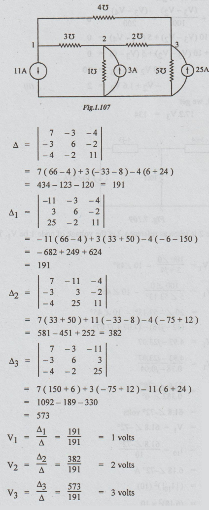
V1
= Δ1 / Δ = 191 / 191 = 1 volts
V2 = Δ2 / Δ = 382
/ 191 = 2 volts
V3 = Δ3
/ Δ = 573 / 191 = 3volts
Electric Circuit Analysis: Unit I: b. Basic circuits analysis : Tag: : ideal voltage source is connected between two nodes - Worked Problems: AC circuits by nodal analysis method when ideal voltage source
Related Topics
Related Subjects

Electric Circuit Analysis
EE3251 2nd Semester 2021 Regulation | 2nd Semester EEE Dept 2021 Regulation