Electrical Machines II: UNIT I: a. Synchronous Generator
Working Principle
Synchronous Generator
Consider a relative motion of a single conductor under the magnetic field produced by two stationary poles.
Working Principle
The
alternators work on the principle of electromagnetic induction. When there is a
relative motion between the conductors and the flux, e.m.f. gets induced in the
conductors. The d.c. generators also work on the same principle. The only
difference in practical alternator and a d.c. generator is that in an
alternator the conductors are stationary and field is rotating. But for
understanding purpose we can always consider relative motion of conductors with
respect to the flux produced by the field winding.
Consider
a relative motion of a single conductor under the magnetic field produced by
two stationary poles. The magnetic axis of the two poles produced by field is
vertical, shown dotted in the Fig. 1.9.1.
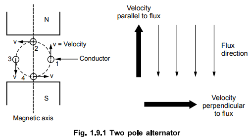
Let
conductor starts rotating from position 1. At this instant, the entire velocity
component is parallel to the flux lines. Hence there is no cutting of
flux lines by the conductor. So dϕ/dt at
this instant is zero and hence induced e.m.f. in the conductor is also zero.
As
the conductor moves from position 1 towards position 2, the part of the
velocity component becomes perpendicular to the flux lines and proportional to
that, e.m.f. gets induced in the conductor. The magnitude of such an induced
e.m.f. increases as the conductor moves from position 1 towards 2.
At
position 2, the entire velocity component is perpendicular to the flux lines.
Hence there exists maximum cutting of the flux lines. And at this instant, the
induced e.m.f. in the conductor is at its maximum.
As
the position of conductor changes from 2 towards 3, the velocity component
perpendicular to the flux starts decreasing and hence induced e.m.f. magnitude
also starts decreasing. At position 3, again the entire velocity component is
parallel to the flux lines and hence at this instant induced e.m.f. in the
conductor is zero.
As
the conductor moves from position 3 towards 4, the velocity component
perpendicular to the flux lines again starts increasing. But the direction of
velocity component now is opposite to the direction of velocity component
exsisting during the movement of the conductor from position 1 to 2. Hence an
induced e.m.f. in the conductor increases but in the opposite direction.
At
position 4, it achieves maxima in the opposite direction, as the entire
velocity component becomes perpendicular to the flux lines.
Again
from position 4 to 1, induced e.m.f. decreases and finally at position 1, again
becomes zero. This cycle continues as conductor rotates at a certain speed.
So
if we plot the magnitudes of the induced e.m.f. against the time, we get an
alternating nature of the induced e.m.f. as shown in the Fig. 1.9.2.
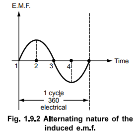
This
is the working principle of an alternator.
1. Mechanical and Electrical Angle
We
have seen that for 2 pole alternator, one mechanical revolution corresponds to
one electrical cycle of an induced e.m.f. Now consider 4 pole alternator i.e.
the field winding is designed to produce 4 poles. Due to 4 poles, the magnetic
axis exists diagonally shown dotted in the Fig. 1.9.3.
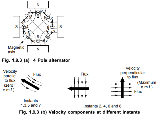
Now
in position 1 of the conductor, the velocity component is parallel to the flux
lines while in position 2, there is gathering of flux lines and entire velocity
component is perpendicular to the flux lines. So at position 1, the induced
e.m.f. in the conductor is zero while at position 2, it is maximum. Similarly
as conductor rotates, the induced e.m.f. will be maximum at positions 4, 6 and
8 and will be minimum at positions 3, 5 and 7. So during one complete
revolution of the conductor, induced e.m.f. will experience four times maxima,
twice in either direction and four times zero. This is because of the
distribution of flux lines due to existence of four poles.
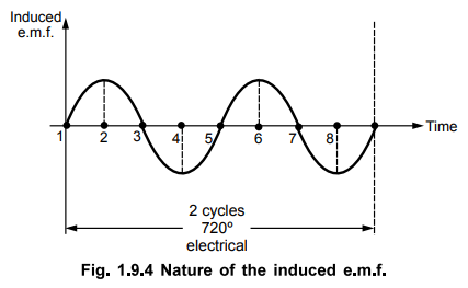
So
if we plot the nature of the induced e.m.f; for one revolution of the
conductor, we get the two electrical cycles of the induced e.m.f., as shown in
the Fig. 1.9.4.
Key Point : Thus the degrees
electrical of the induced e.m.f i.e. number of cycles of the induced e.m.f.
depends on the number of poles of an alternator.
So
for a four pole alternator we can write,
360°
mechanical = 720° electrical
From
this we can establish the general relation between degrees mechanical and
degrees electrical as,
360°
mechanical = 360° × P/2 electrical
Where,
P = Number of poles
i.e.
1o mechanical = (P/2)oelectrical
2. Frequency of Induced E.M.F.
Let P = Number of poles
N
= Speed of the rotor in r.p.m.
and f = Frequency of the induced e.m.f.
From
the discussion, we can write,
One
mechanical revolution of rotor = P/2 cycles of e.m.f. electrically
Thus
there are P/2 cycles per revolution.
As
speed is N r.p.m., in one second, rotor will complete (N/60) revolutions.
But
cycles/sec. = Frequency = f
Frequency
f = (No. of cycles per revolution) × (No. of revolutions per second) ,
f
= P/2 × N/60
•
f = PN/120 Hz(cycles per sec).
So
there exists a fixed relationship between three quantities, the number of poles
P, the speed of the rotor N in r.p.m. and f the frequency of an induced e.m.f.
in Hz (Hertz).
Key Point : Such a
machine bearing a fixed relationship between P, N and f is called synchronous
machine and hence alternators are also called synchronous generators.
3. Synchronous Speed (NS)
From
the above expression, it is clear that for fixed number of poles, alternator
has to be rotated at a particular speed to keep the frequency of the generated
e.m.f. constant at the required value. Such a speed is called synchronous speed
of the alternator denoted as Ns.
So
Ns = 120f/P
Where
f = Required frequency
In
our nation, the frequency of an alternating e.m.f. is standard equal to 50 Hz.
To get 50 Hz frequency, for different number of poles, alternator must be
driven at different speeds called synchronous speeds. Following table gives the
values of the synchronous speeds for the alternators having different number of
poles.
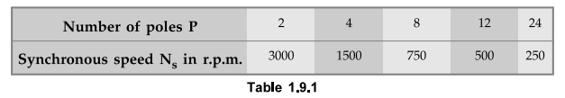
From
the table, it can be seen that minimum number of poles for an alternator can be
two hence maximum value of synchronous speed possible in our nation i.e. for
frequency of 50 Hz is 3000 r.p.m.
Review Questions
1. Explain the working principle of an alternator.
2. Derive the relation between degrees electrical and degrees
mechanical.
3. Obtain the relation between frequency and speed of an
alternator.
Electrical Machines II: UNIT I: a. Synchronous Generator : Tag: Engineering Electrical Machines - II : Synchronous Generator - Working Principle
Related Topics
Related Subjects

Electrical Machines II
EE3405 Machine 2 EM 2 4th Semester EEE Dept | 2021 Regulation | 4th Semester EEE Dept 2021 Regulation