Electrical Machines II: UNIT III: a. Three Phase Induction Motor
Working Principle of Three Phase Induction Motor
The speed of this rotating magnetic field is synchronous speed, NS r.p.m.
Working Principle AU
: Dec.-05, 06, 11, 12, 13, 14, 15,17, May-10, 11,18
Induction
motor works on the principle of electromagnetic induction.
When
a three phase supply is given to the three phase stator winding, a rotating
magnetic field of constant magnitude is produced as discussed earlier. The
speed of this rotating magnetic field is synchronous speed, NS
r.p.m.
NS
= 120 f / P = Speed of rotating magnetic field
where
f = Supply frequency
P
= Number of poles for which stator winding is wound.
This
rotating field produces an effect of rotating poles around a rotor. Let
direction of rotation of this rotating magnetic field is clockwise as shown in
the Fig. 5.5.1 (a).
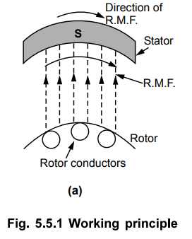
Now
at this instant rotor is stationary and stator flux R.M.F. is rotating.
So its obvious that there exists a relative motion between the R.M.F. and rotor
conductors. Now the R.M.F. gets cut by rotor conductors as R.M.F. sweeps over
rotor conductors. Whenever conductor cuts the flux, e.m.f. gets induced in it.
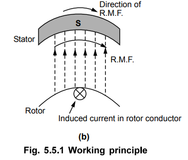
So e.m.f. gets induced in the rotor conductors called rotor induced e.m.f.
This is electro-magnetic induction. As rotor forms closed circuit, induced
e.m.f. circulates current through rotor called rotor current as shown in the
Fig. 5.5.1 (b). Let direction of this current is going into the paper denoted
by a cross as shown in the Fig. 5.5.1 (b).
Any
current carrying conductor produces its own flux. So rotor produces its flux
called rotor flux. For assumed direction of rotor current, the direction of
rotor flux is clockwise as shown in the Fig. 5.5.1 (c).
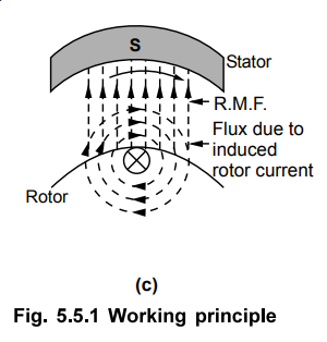
This
direction can be easily determined using right hand thumb rule. Now there are
two fluxes, one R.M.F. and other rotor flux. Both the fluxes interact with each
as shown in the Fig. 5.5.1 (d).
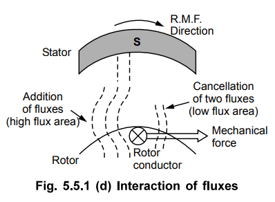
On
left of rotor conductor, two fluxes are in same direction hence add up to get
high flux area. On right side, two fluxes cancel each other to produce low flux
area. As flux lines act as stretched rubber band, high flux density area exerts
a push on rotor conductor towards low flux density area. So rotor conductor
experiences a force from left to right in this case, as shown in the Fig. 5.5.1
(d), due to interaction of the two fluxes.
As
all the rotor conductors experience a force, the overall rotor experiences a
torque and starts rotating. So interaction of the two fluxes is very
essential for a motoring action. As seen from the Fig. 5.5.1 (d), the
direction of force experienced is same as that of rotating magnetic field.
Hence rotor starts rotating in the same direction as that of rotating magnetic
field.
Alternatively
this can be explained as : According to Lenz's law the direction of induced
current in the rotor is so as oppose the cause producing it. The cause of rotor
current is the induced e.m.f. which is induced because of relative motion
present between the rotating magnetic field and the rotor conductors. Hence to
oppose the relative motion i.e. to reduce the relative speed, the rotor
experiences a torque in the same direction as that of R.M.F. and tries to catch
up the speed of rotating magnetic field.
So, Ns = Speed of rotating magnetic
field in r.p.m.
N
= Speed of rotor i.e. motor in r.p.m.
Ns
- N = Relative speed between the two,
rotating
magnetic field and the rotor conductors.
Thus
rotor always rotates in same direction as that of R.M.F.
1. Can N = Ns?
When
rotor starts rotating, it tries to catch the speed of rotating magnetic field.
If
it catches the speed of the rotating magnetic field, the relative motion
between rotor and the rotating magnetic field will vanish (Ns - N =
0). In fact the relative motion is the main cause for the induced e.m.f. in the
rotor. So induced e.m.f. will vanish and hence there cannot be rotor current
and the rotor flux which is essential to produce the torque on the rotor.
Eventually motor will stop. But immediately there will exist a relative motion
between rotor and rotating magnetic field and it will start. But due to inertia
of rotor, this does not happen in practice and rotor continues to rotate with a
speed slightly less than the synchronous speed of the rotating magnetic field
in the steady state. The induction motor never rotates at synchronous speed.
The speed at which it rotates is hence called subsynchronous speed and
motor sometimes called asynchronous motor.
N
< Ns
So
it can be said that rotor slips behind the rotating magnetic field produced by
stator. The difference between the two is called slip speed of the
motor.
Ns
- N = Slip speed of the motor in r.p.m.
This
speed decides the magnitude of the induced e.m.f. and the rotor current, which
in turn decide the torque produced. The torque produced is as per the
requirements of overcoming the friction and iron losses of the motor along with
the torque demanded by the load on the motor.
Review Questions
1. Describe the principle of operation of a 3 phase induction
motor with a neat sketch. Explain why a rotor is forced to rotate in the
direction cf rotating magnetic field. AU : Dec.-05, 06, 11, 12, 13, 14, 15, 17,
May-10, 11,18, Marks 8
2. Can induction motor rotate at synchronous speed ? Why ?
Electrical Machines II: UNIT III: a. Three Phase Induction Motor : Tag: Engineering Electrical Machines - II : - Working Principle of Three Phase Induction Motor
Related Topics
Related Subjects

Electrical Machines II
EE3405 Machine 2 EM 2 4th Semester EEE Dept | 2021 Regulation | 4th Semester EEE Dept 2021 Regulation