Electron Devices and Circuits: Unit I: PN Junction Devices
Zener Voltage Regulator
Circuit Diagram, VI Characteristics, Solved Example Problems
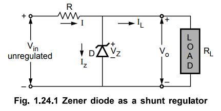
• The simplest shunt voltage regulator circuit uses a zener diode, to regulate the load voltage. The Fig. 1.24.1 shows the arrangement of zener diode in a regulator circuit.
Zener Voltage Regulator
AU
: May-08,12,13,14,15,16,17, Dec.-09,10,17,18
•
The simplest shunt voltage regulator circuit uses a zener diode, to regulate
the load voltage. The Fig. 1.24.1 shows the arrangement of zener diode in a
regulator circuit.
•
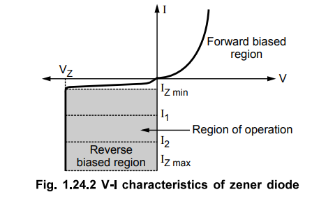
To understand the working of the circuit, let us revise the V-I characteristics
of a zener diode, as shown in the Fig. 1.24.2.
•
The zener diode is used in its reverse biased region. Under reverse biased
condition, the current through the diode is very small of the order of few u.A,
upto certain limit. When the sufficient reverse bias is applied, electrical
breakdown of the zener diode occurs. The large current flows through the zener
diode. Such a breakdown occurs at a voltage called zener voltage VZ-
Under this condition, whatever may be the current, the voltage across the zener
is constant equal to VZ. The large current due to breakdown is
limited by connecting the resistance in the circuit.
•
As the voltage across the zener diode remains constant equal to VZ,
it is connected across the load and hence the load voltage Vo is equal to the
zener voltage VZ . Thus zener diode acts as an ideal voltage source
which maintains a constant load voltage, independent of the current.
1. Regulation with Varying Input Voltage
•
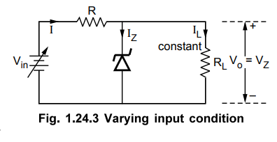
The Fig. 1.24.3 shows a zener regulator under varying input voltage condition.
•
It can be seen that the output is
Vo
= Vz is constant.
IL
= Vo / RL Vz /
RL = Constant
And I = IZ + IL
•
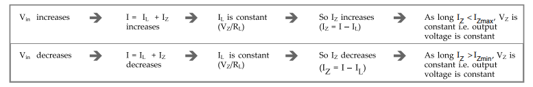
Now if Vin increases, then
the total current I increases. But IL is constant as Vz is
constant. Hence the current Iz increases to keep IL
constant.
•
But as long as IZ is between IZmin and IZmax,
the VZ i.e. output voltage Vo is constant. Thus the
changes in input voltage get compensated and output is maintained constant.
•
Similarly if decreases, then current I decreases. But to keep IL constant, Iz
decreases. As long as Iz is between IZmax and IZmin, the output voltage remains
constant.
•
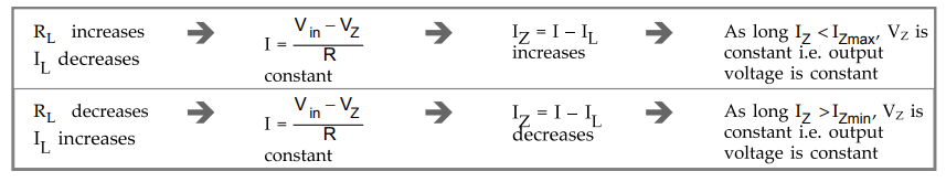
Process flow chart for zener regulator under varying Vin is,
•
The maximum power dissipation for the zener diode is fixed and given by,
PD
= VZ IZmax
Ex.
1.24.1 Over what range of input voltage will the zener in a voltage regulator
in circuit maintain 30 V across 2000 Ω load, assuming that series resistance R
= 200 Ω and zener current rating is 25 mA ?
Sol
: This circuit is shown in the Fig. 1.24.A
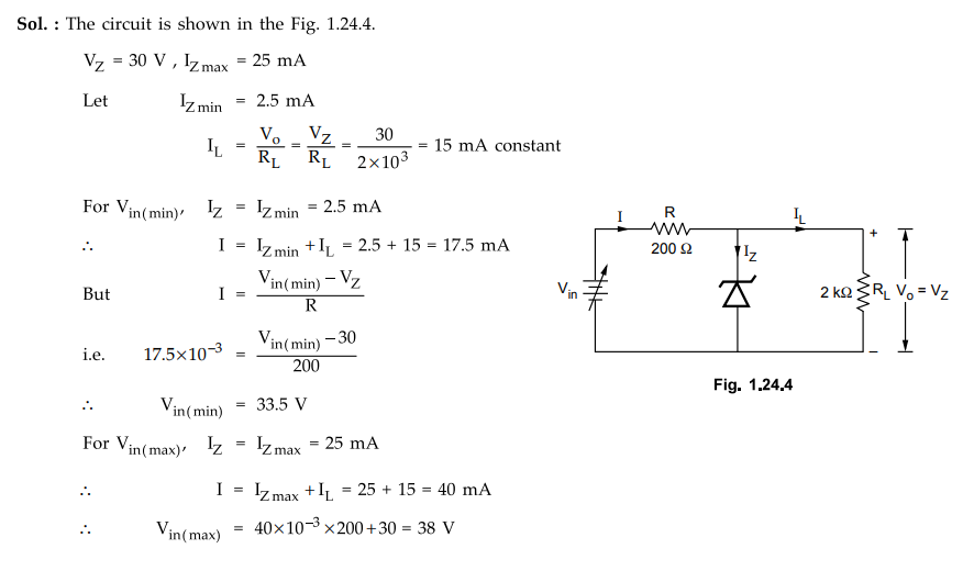
Thus
the range of input voltage is 33.5 V to 38 V for which the circuit will work as
regulator.
Ex.
1.24.2 Design a zener regulator for the following specifications
Output
voltage, Vo = 5 V, Input voltage, = Vt = 12 ± 3, IZmin
= 10 mA
Load
current, IL = 20 mA, Zener wattage, PZ = 500 mW
Sol-:
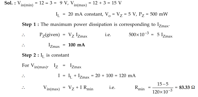
When
R = Rmin, for the current I will be
at its maximum i.e. IZ will be at its maximum.
Step
3 :
To calculate Rmax, I must be minimum i.e. IZ must be minimum i.e. 10
mA.
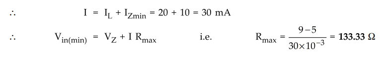
Thus
R must be greater than 83.33 Ω and less than 133.33 Ω for proper regulating
action.
2. Regulation with Varying Load
•
The Fig. 1.24.5 shows a zener regulator under varying load condition and
constant input voltage.
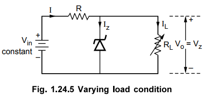
•
The input voltage is constant while the load resistance RL is
variable. As V. is constant and Vo = Vz is constant, then
for constant R the current I is constant.
I
= Vin – Vz / R constant = IL + Iz
•
Now if RL decreases so IL increases, to keep I constant
Iz
decreases. But as long as it is between IZmin and IZmax
output voltage Vo will be constant. Similarly if RL increases so IL
decreases, to keep I constant Iz increases. But as long as it is between IZmin
and IZmax' outPut voltage Vo will be constant.
•
Process flow chart for zener regulator under varying load is,
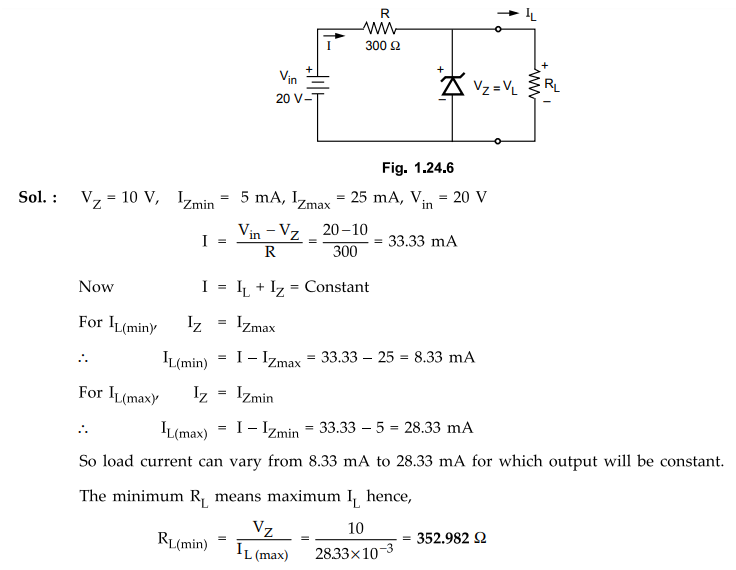
Ex.
1.24.3 Determine the minimum and the maximum load currents for which the zener
diode in Fig . 1.24.6 will maintain regulation. What is the minimum RL
that can be used? VZ = 10 V, IZmin = Assume rZ = 0 Ω
Ex.
1.24.4 For the following circuit, find the maximum and minimum values of Zener
diode current.
AU
: Dec.-18, Marks 6
Sol.
:
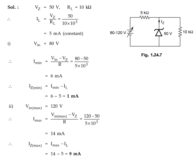
Thus
minimum and maximum valves of zener diode current are 1 mA and 9 mA
respectively.
Review Questions
1. Explain the working of a zener diode as a shunt regulator.
AU : Hay-08, 12, 13, 14, 15, 17, Dec.-O9, 10, 18, Harks 8
2. Explain the VI characteristics of Zener diode.
AU : Hay-16, Harks 8
3. In a shunt voltage regulator using zener diode, calculate
minimum and maximum values of current limiting resistor (R).
Given : Vz = 8 V, Source voltage = 30 V, Load current
= 0-50 mA, IZmin = 5 mA, PZmax = 1 W.
4. In a shunt regulator circuit using zener diode, the series
resistance used is 1.2 kW. It provides 4.7 V to a load of 2.2 kW. If IZmin is 1
mA and IZmax is 20 mA, what is the range of the input voltage for the output
voltage to remain constant ?
5. There is an application which needs the output voltage to be
regulated. Choose an appropriate diode/device, that would ensure this operation
with appropriate circuit, describe how it regulates voltage. Consider a
specific example, design the circuit with appropriate values of components
involved. State the important constraints that need to be considered.
Electron Devices and Circuits: Unit I: PN Junction Devices : Tag: : Circuit Diagram, VI Characteristics, Solved Example Problems - Zener Voltage Regulator
Related Topics
Related Subjects

Electron Devices and Circuits
EC3301 3rd Semester EEE Dept | 2021 Regulation | 3rd Semester EEE Dept 2021 Regulation