Microprocessors and Microcontrollers: Unit IV: (e) Keyboard and Display Controller - 8279
8279 Commands
Keyboard and Display Controller - 8279
In the last sections we have seen various operating modes of 8279. To program 8279 in the desired mode it provides eight command words.
8279 Commands
In
the last sections we have seen various operating modes of 8279. To program 8279
in the desired mode it provides eight command words. The command words are sent
on the data bus with ![]() low and A0 high and are loaded to the
8279 on the rising edge of
low and A0 high and are loaded to the
8279 on the rising edge of ![]() . 8279 differentiate these commands by
checking 3 most significant bits of the command word.
. 8279 differentiate these commands by
checking 3 most significant bits of the command word.
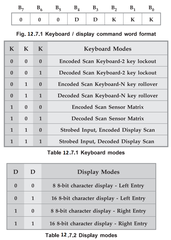
1. Keyboard / Display Mode Set Command (000)
This
command is used to program operating modes of keyboard and display. Three least
significant bits decide the keyboard mode and next two bits decide the display
mode, as shown in the tables.
Command
Word Format
Example
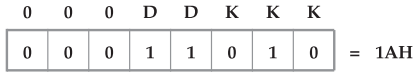
12.7.1 Give the command word to set keyboard / display mode
for the following configuration.
Encoded
scan keyboard – N key rollover
16
8-bit character display – Night Entry
Solution
: Command word :
Example
12.7.2 The microprocessor system has a configuration given
below. Find the keyboard / display command word.
8
× 4 matrix keyboard - 2 key lockout
4
Digit 7-segment display left entry
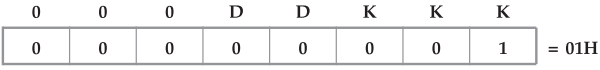
Solution
:
The system has 8 × 4 matrix keyboard and 4 digit display. Hence, only 4 scan
lines are sufficient. The decoded mode of 8279 provides 4 scan lines directly
and these lines can be used directly to interface 8 × 4 matrix keyboard and 4
digit display without external decoder. Therefore, we should select keyboard
and display modes as:
Keyboard
mode : Decoded scan keyboard - 2 key lockout
Display
mode : 8-bit character display left entry
Command
word :
2. Program Clock Command (001)
All
timing and multiplexing signals for the 8279 are generated by an internal
prescaler. This prescaler divides the external clock by a programmable integer
value given in the program clock command word, to generate internal frequency.
Fig. 12.7.2 shows format for program clock command word.
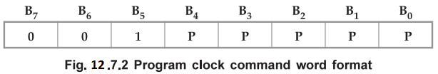
Bits
PPPPP determine the value of this integer which ranges from 2 to 31. To give
proper scan and key debounce times the internal frequency should be 100 kHz.
Therefore, prescaler integer value should be selected to get 100 kHz internal
frequency.
Prescaler
value = External clock / 100 kHz
Example
12.7.3 Find the program clock command word if external
clock frequency is 2 MHz.
Solution
:
Prescaler value = 2 × 10⁶ / 100 ×
103 = 20 = (10100)2
Command
word = (00110100)2 = 34H
3. Read FIFO / Sensor RAM Command (010)
To
read data from FIFO/Sensor RAM, it is necessary to set 8279 in read FIFO/sensor
RAM mode. Read FIFO/Sensor RAM command is used for this purpose. Fig. 12.7.3
shows the format for Read FIFO/Sensor RAM command.
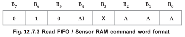
Here,
three least significant bits, (AAA) specify the address of the sensor RAM and
bit B4, if 1 enables autoincrement mode. In the scan keyboard mode,
the autoincrement flag (AI) and the FIFO RAM address bits (AAA) are irrelevant.
In this mode, 8279 provides data for each subsequent read in the same sequence
in which the data first entered in the FIFO RAM.
In
the sensor matrix mode, the sensor RAM address bits AAA select one of the 8
rows of the sensor RAM. If the autoincrement flag is set (AI = 1), each
successive read will be from the subsequent row of the sensor RAM.
Example
12.7 4 Write a command word to read data from FIFO RAM.
Solution
:
We know that, in scan keyboard mode, the autoincrement flag (AI) and the FIFO
RAM address bits (AAA) are irrelevant. Therefore, command word to read data
from FIFO RAM is as given below.
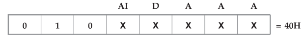
Note
X
= Don't care. Taking don't cares equal to zeros we get command word to read
data from FIFO RAM is 40H.
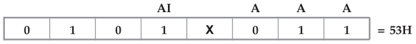
Example
12.7.5 Write a command word to read third location with
autoincrement of the sensor RAM in sensor matrix mode.
Solution
: Command word :
4. Read Display RAM Command (011)
To
read data from display RAM, it is necessary to set 8279 in read display RAM
mode. Read display RAM command is used for this purpose. Fig. 12.7.4 shows the
format for Read Display RAM command.
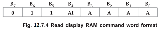
Here,
four least significant bits (AAAA) specify the address of the 16 byte display
RAM and bit B4, if 1, enables autoincrement mode. If the bit B4
(AI) is set, display RAM address is incremented after each read command to
display RAM.
Example
12.7.6 Write a command word to read fourth location with
autoincrement of the display RAM.
Solution
: Command word :

5. Write Display RAM Command (100)
To
write data into display RAM, it is necessary to set 8279 in write display RAM
mode. Write display RAM command is used for this purpose. Fig. 12.7.5 shows the
format for Write display RAM command.
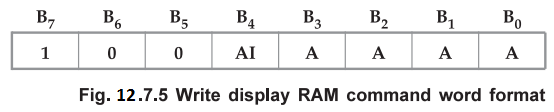
Here,
four least significant bits (AAAA) specify the address of the 16 byte display
RAM and bit B4, if 1, enables autoincrement mode. If the bit B4 (AI) is set, display RAM address is
incremented after each write command to display RAM.
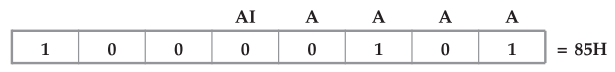
Example
12.7.7 Write a command word to write fifth location without
autoincrement of the display RAM.
Solution
: Command word :
6. Display Write Inhibit / Blanking Command (101)
We
know that, display RAM data is sent on the two 4-bit ports (B3-B0 and A3-A0)
This two 4-bit pots can be individually inhibited or blanked with Display Write
Inhibit/Blanking command. Fig. 12.7.6 shows the format for Display Write
Inhibit/Blanking Command.
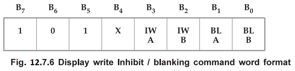
The
IW bits are used to mask nibble. A (4-bit port A) and nibble B (4-bit port B)
in applications requiring separate 4-bit display ports. By setting the IW flag
(I/W = 1) for one of the ports, the port can be masked so that entries to the
display RAM from the CPU do not affect other port.
The
BL bits are used to blank the individual nibbles. This command loads the blank
code (All zeros, 20H, or All ones) determined by the last issued clear command,
in the display RAM to blank the display.
Note
After
reset blank code is set to all zeros.
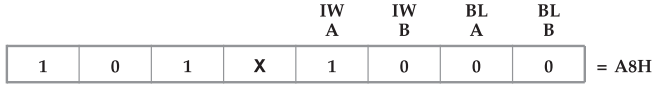
Example
12.7.8 Write a command word to inhibit nibble A of the
display.
Solution
: Command word :
7. Clear Command (110)
Clear
command is used to clear all the rows of the display RAM with a selectable
blanking code, to clear status of FIFO RAM and to reset interrupt output line.
Fig. 12.7.7 shows the format of clear command.
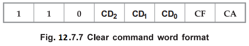
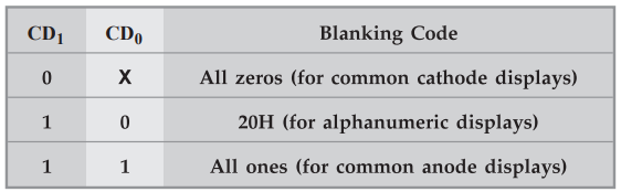
CD
bits (CD0 -CD1) are used to select the blanking code as
given below
Bit
CD2, when set to one, enables clear display.
Bit
CF, when set to one, clears the status of the FIFO, resets the interrupt output
line and sets the sensor RAM address to 000.
CA,
the clear all bit, has the combined effect of CD and CF; it uses the CD
clearing code on the displays RAM and also clears FIFO status. It also
resynchronizes the internal timing chain.
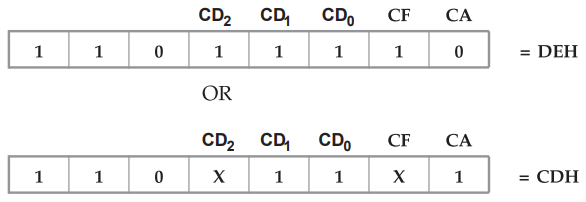
Example
12.7.9 Write a command word to set blanking code for common
anode display and to clear the FIFO status.
Solution
:
Blanking code for common anode display is all ones and which can be set by
writing CD1 = 1 and CD2
8. End Interrupt / Error Mode Set Command (111)
In
the sensor matrix mode, if any change in sensor value is detected, IRQ line
goes high at the end of a sensor matrix scan. The IRQ line is cleared by the
first data read operation if the autoincrement flag is set to zero. But if
autoincrement flag is set to one then it is necessary to issue End Interrupt
Command to clear the IRQ line. Fig. 12.7.8 shows the format for End
Interrupt/Error mode set command.
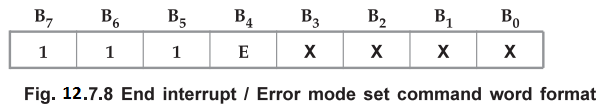
For
the N key rollover mode, if the E bit is programmed to T', the 8279 will
operate in the Special Error Mode. In the special error mode, if two keys are
depressed during single debounce, the error flag in the FIFO status word is
set.
Example
12.7.10 Write a command word to clear IRQ line
in a sensor matrix mode.
Solution
: Command word :
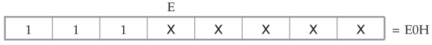
Note
Status
of E bit can be 0 or 1.
FIFO
STATUS REGISTER
It
is used in the keyboard and strobed input modes to indicate the number of
characters in the FIFO and to indicate whether an error has occurred. Fig. 12.7.9
shows the format of FIFO status word.
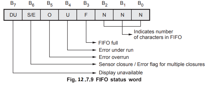
As
shown in the Fig. 12.7.9, there are two types of possible errors : Overrun and
underrun. Overrun error occurs when the entry of another character into a full
FIFO is attempted. Underrun occurs when the CPU tries to read an empty FIFO.
During
clear display or clear all command, display RAM is not available for user. This
is indicated DU bit in the FIFO status register.
In
the sensor matrix mode, a S/E bit is set in the FIFO status word to indicate
that at least one sensor closure indication is contained in the sensor RAM.
In
the special error mode, a S/E bit is set in the FIFO status word to indicate
that a simultaneous multiple closure error has occurred.
Review Questions
1. Explain various
command word formats of 8279.
2. Explain the working
of 8279 as a keyboard/display controller and explain its command registers
AU : Dec.-16, Marks 16
Microprocessors and Microcontrollers: Unit IV: (e) Keyboard and Display Controller - 8279 : Tag: : Keyboard and Display Controller - 8279 - 8279 Commands