Microprocessors and Microcontrollers: Unit IV: (e) Keyboard and Display Controller - 8279
Keyboard Interfacing
Microprocessors and Microcontrollers
1. Key Debounce using Hardware 2. Key Debouncing using Software 3. Simple Keyboard Interface 4. Matrix Keyboard Interface
Keyboard Interfacing
For
interfacing keyboard to the microprocessor based systems, usually push button
keys are used. These push button keys when pressed, bounces a few times,
closing and opening the contacts before providing a steady reading, as shown in
the Fig. 12.1.1. Reading taken during bouncing period may be faulty. Therefore,
microprocessor must wait until the key reach to a steady state; this is known
as key debounce.

The
problem of key bounce can be eliminated using key debounce technique, either
hardware or software.
1. Key Debounce using Hardware
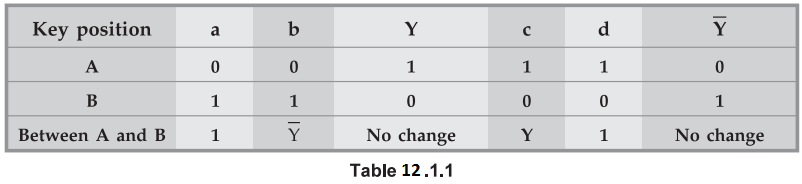
Fig.
12.1.2 shows the circuit diagram of key debounce. It consists of flip-flop. The
output of flip-flop shown in Fig. 12.1.2 is logic 1 when key is at position A
(impressed) and it is logic 0 when key is at position B, as shown in Table 12.1.1.
It is important to note that, when key is in between A and B, output does not
change, preventing bouncing of key output.
In
other words we can say that output does not change during transition period,
eliminating key debouncing.

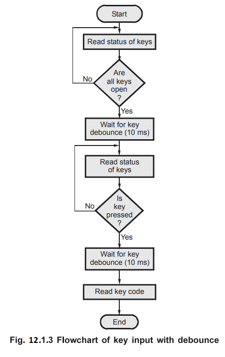
2. Key Debouncing using Software
In
the software technique, when a key press is found, the microprocessor waits for
at least 10 ms before it accepts the key as an input. This 10 ms period is
sufficient to settle key at steady state. Fig. 12.1.3 shows the flowchart with
key debounce technique.
3. Simple Keyboard Interface
Fig.
12.1.4 shows simple keyboard interface.

Here eight keys are individually connected to specific pins of input port. Each port pin gives the status of key connected to that pin. When port pin is logic 1, key is open, otherwise key is closed.
Software
routine to get keycode with key debounce.
START
: IN IN_PORT ; Read key status
CPI FFH ; check if keys are open
JNZ START ; if no, goto start otherwise continue
CALL DEBOUNCE_DELAY ; call debounce delay
AGAIN
: IN IN PORT ; Read key status
CPI FFH ; check if any key is pressed
JZ AGAIN ; if no, goto AGAIN ; otherwise continue
CALL DEBOUNCE_DELAY ; call debounce delay
IN IN PORT ; Get key code
RET ; Return from subroutine
This
program reads status of all keys by getting data through port IN_PORT and
compares it with FFH to check whether all keys are open. If all keys are open,
instruction CPI sets the zero flag, and the program waits for key debounce.
After waiting about 10 ms, program checks the IN_PORT for key press. If key
press is found, program waits for another 10 ms as a key debounce period. After
key debounce period, program reads the keycode from port IN_PORT.

4. Matrix Keyboard Interface
In
simple keyboard interface one input line is required to interface one key and
this number will increase with number of keys. Therefore, such technique is not
suitable when it is necessary to interface large number of keys. To reduce
number of connections keys are arranged in the matrix form as shown in the Fig.
12.1.5.

Fig.
12.1.5 shows sixteen keys arranged in
four rows and four columns. When keys are open, row and column do not have any
connection.
When
a key is pressed, it shorts corresponding one row and one column. This matrix
keyboard requires eight lines to make all the connections instead of the sixteen
lines required if the keys are connected individually, as shown in Fig. 12.1.5.

Fig.
12.1.6 shows the interfacing of matrix
keyboard. It requires two ports : an input port and an output port. Rows are connected
to the input port referred to as returned lines, and columns are connected to
the output port referred to as scan lines. We know that, when all keys are
open, row and column do not have any connection. When any key is pressed it
shorts corresponding row and column. If the output line of this column is low,
it makes corresponding row line low; otherwise the status of row line is high.
The key is identified by data sent on the output port and input code received
from the input port. The following section explains the steps required to
identify pressed key.
Check
1 :
Whether any key is pressed or not
1.
Make all column lines zero by sending low on all output lines. This activates
all keys in the keyboard matrix. (Note : When scan lines are logic high,
the status on the return lines do not change, it will remain logic high.)
2.
Read the status of return lines. If the status of all lines is logic high, key
is not pressed; otherwise key is pressed.
Check
2 :
1.
Activate keys from any one column by making any one column line zero.
2.
Read the status of return lines. The zero on any return line indicates key is
pressed from the corresponding row and selected column. If the status of all
lines is logic high, key is not pressed from that column.
3.
Activate the keys from the next column and repeat 2 and 3 for all columns.
Lab Experiment 12.1.1 : Hardware and
software for 64-key matrix keyboard interface
Statement :
Interface 64-key matrix keyboard to the 8085 microprocessor using 8255. Write
an 8085 assembly language program to initialize 8255 and to read the key code.

Hardware
: Fig. 12.1.7 shows a matrix keyboard with 64 keys connected to the 8085
microprocessor using 8255. A matrix keyboard reduces the number of connections,
thus the number of interfacing lines. In this example, the keyboard with 64
keys, is arranged in 8 × 8 (8 rows and 8 columns) matrix. This requires sixteen
lines from the microprocessor to make all the connections instead of 64 lines
if the keys are connected individually. The interfacing of matrix keyboard
requires two ports : one input port and other output port. Rows are connected
to the input port, port A and columns are connected to the output port, port B.
Source
program :
MVI
A, 90H ; Initialize Port A as
input and Port B as
OUT
CR ; Output
START
: MVI A, 00
OUT PB ; Make all scan lines zero
BACK
: IN PA
CPI
FF ; Check for key release
JNZ
BACK ; If not, wait for key release
CALL
DELAY ; Wait for key debounce
BACK_1
: IN PA
CPI
FF ; Check for key press
JZ
BACK_1 ; If not, wait for key
press
CALL
DELAY ; Wait for key debounce
MVI
L, 00H ; Initialize key
;
counter
MVI
C, 08H
MVI
B, FEH ; Make one
;
column low
NEXTCOL
: MOV A, B
OUT
PB
MVI
D, 08H ; Initialize row
;
counter
IN
PA ; Read return
;
line status
NEXTROW
: RRC ; Check for one row
JNC
DISPLAY ; If zero, goto
;
display
;
otherwise
;
continue
INR
L ; Increment key
;
counter
DCR
D ; Decrement
;
row counter
JNZ
NEXTROW ; Check for next
;
row
MOV
A,B
RLC
; Select the next
;
column
MOV
B,A
DOR
C ; Decrement
;
column count
JNZ
NEXTCOL ; Check for last
;
column if not repeat
JMP
START ; Goto start

Review Questions
1. What is keyboard
interfacing? AU : May-12, Marks 2
2. Design an 8085
based system with external Keyboard. AU : May-18, Marks 5
Microprocessors and Microcontrollers: Unit IV: (e) Keyboard and Display Controller - 8279 : Tag: : Microprocessors and Microcontrollers - Keyboard Interfacing