Transmission and Distribution: Unit V: (a) Distribution Systems
A.C. Distribution
Calculations - Methods of Solving - Power Factors Referred to Respective Load Voltages
Questions : 1. Draw and explain the phasor diagram for an a.c. distributor with power factors referred to the receiving end voltage. 2. Draw and explain the phasor diagram for an a.c. distributor with power factors referred to the respective load voltages. 3. A single phase a.c. distributor AB has length cf 300 m and is fed from end A and is loaded as under : i) 100 A at 0.707 pf. lagging 200 m from point A ii) 200 A at 0.8 p.f. lagging 300 m from point A The total resistance and reactance of the distributor is 0.2 Ω and 0.1 Ω per kilometer. Calculate the voltage drop in the distributor. The load power factors refer to the voltage at the far end.
A.C. Distribution
In earlier days, d.c. system was used
for the generation, transmission and distribution of electrical energy. But in
case of d.c. system the voltage level cannot be changed easily unless we used
rotating machinary which may not prove to be economical in many cases. This is
the major disadvantage while working with d.c.
Later on with the development of
transformer, a.c. system has become predominant. Now a days large power systems
in the world are using a.c. system rather than d.c. because of many advantages
of a.c. system.
The transmission of electrical energy
generated in the power station is at very high voltage with the use of 3 phase,
3 wire system. These voltages are stepped down for distribution at the
substations. There are mainly two parts of the distribution system. They are
primary distribution and secondary distribution. The voltage level of primary
distribution system is higher than general utilisation level. The secondary
distribution systems receive power from primary distribution systems through
distribution transformers. By distribution transformer voltage is stepped down
to the normal working level and the consumers get the power with the voltage
400/230 V. The very commonly used a.c. distribution system is three phase four
wire system as studied earlier.
1. A.C. Distribution Calculations
The A.C. distribution calculations and
d.c. distribution calculations are different in the following respects :
1. In case of d.c. system, the voltage
drop is due to resistance only which in a.c. system it is due to combined
effect of resistance, inductance and capacitance.
2. The voltages or currents are added or
subtracted arithmetically in case of d.c. system whereas they are added or
subtracted vectorially in case of a.c. system.
3. It is required to take into account
the power factor while making calculations in a.c. system which is absent in
d.c. system. The distributors are normally tapped at different points with the
loads having different power factors.
There are two ways of referring the
power factor.
a) The p.f. may be referred to receiving
end voltage which is reference vector.
b) The p.f. may be referred to the
voltage at load point itself.
By different methods the a.c.
distribution problems can be solved.
The most convenient method is the
symbolic notation method wherein voltages, currents and impedances are
expressed in the complex notation and the calculations are similar to those in
case of d.c. distribution. In a.c. calculations, addition and subtraction must
be done by expressing various quantities in the rectangular form while the
multiplication and the division must be done by expressing the various
quantities in the polar form.
2. Methods of Solving A.C. Distribution Problems
As discussed in earlier section in case
of a.c. distribution system we have to take into account the power factor. This
power factor can be either considered with respect to receiving end voltage or
with respect to load voltage itself. Let us consider each case separately.
a. Power Factors Referred to Receiving
End Voltage
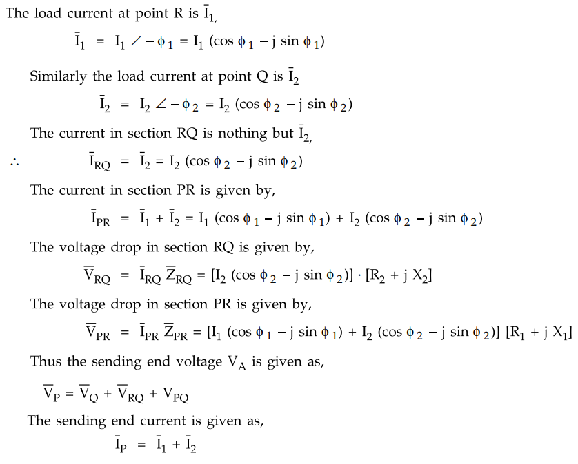
Consider an A.C. distribution PQ having
concentrated loads of and I2 tapped off at point Q and R respectively. This is
shown in the Fig. 7.13.1.

Let voltage VQ which is the
voltage at the receiving end be taken as reference vector.
The power factors at R and Q are cos ϕ1
and cos ϕ2 with respect to VQ and they are lagging.
Let R1
= Resistance of section PR, X1 = Reactance of section PR
R2 = Resistance of section
RQ, X2= Reactance of section RQ
Impedance of section PR is given by, ZPR
= R1 + j X1
Impedance of section RQ is given by, ZRQ
= R2 + j X2
The corresponding diagram is shown in
the Fig. 7.13.2.
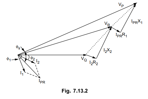
As shown in the Fig. 7.13.2 the
receiving end voltage VQ is taken as reference vector. The currents
I1 and I2 are lagging from VQ by angles of ϕ1
and ϕ2 respectively. The vector sum of I1 and I2
gives current IPR. The drop
I2 R2 is in phase with I2 while I2
X2 is leading by 90°. The vector sum of VQ, I2
R2 and I2 X2 gives VR. The drop IPR
R1 is in phase with current IPR while IPR X1
is leading by 90°. The vector sum of VR, IPR R1
and IPR X1 gives the sending end voltage VP.
3. Power Factors Referred to Respective Load Voltages
In previous section we have considered
the load power factors with respect to receiving end voltage. Here we will
consider these power factors with respect to their respective load voltages.
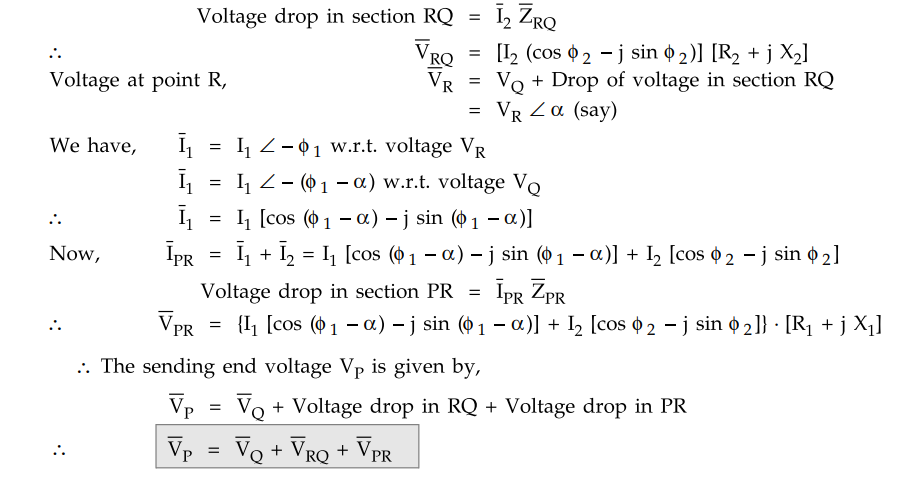
Now ϕ1 is the phase angle between VR and Ix while the angle ϕ 2
is the phase angle between VQ and I2.
The phasor diagram under this condition
will be as shown in the Fig. 7.13.3.
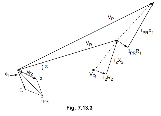
Here again the receiving end voltage VQ
is the reference phasor. The vector sum of I1 and I2
gives the current IPR.
The drop I2 R2 is
in phase with I2 while I2 X2 is leading by 90°. The
vector sum of VQ,
I2 R2 and I2
X2 gives voltage VR. The drop IPR R1
is in phase with current IPR while the drop IPR X-^ is leading by 90°. The
vector sum of VR, IPR R1 and IPR X1
gives the sending end voltage VP.
Now voltage drop in section RQ is given
by,
Example 7.13.1
A single phase distributor ’AB' 300 m long supplies a load of 200 A at 0.8
pf lagging at its far end 'B' and a load of 100 A at 0.707 pf lagging at 200 m
from sending end point A. Both pf are referred to the voltage at the far end.
The total resistance and reactance per km (go and return) of the distributor is
0.2 ohm and 0.1 ohm. Calculate the total voltage drop in the distributor.
Solution :
The arrangement is shown in the Fig. 7.13.4.

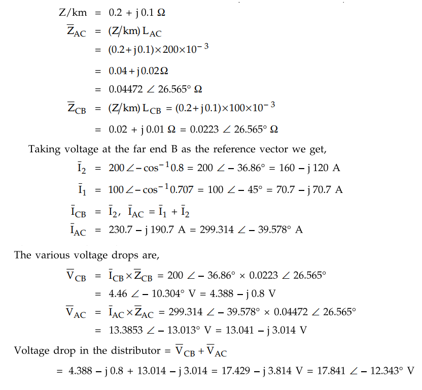
Magnitude of voltage drop in distributor
= 17.841 V
Example 7.13.2
A single phase ring distributor ABC is fed at A. The loads at B and C are 40
A at 0.8 p.f. lagging and 60 A at 0.6 p.f. lagging respectively. Both power
factors expressed are referred to the voltage at point A. The total impedance
of sections AB, BC and CA are (2 + jl), (2 + j3) and (1 + j2) Q respectively.
Determine current in each section.
Solution :
The single phase ring distributor ABC is shown in the Fig. 7.13.5.
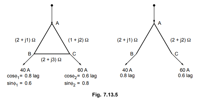
We use Thevenin's Theorem to solve this
problem. First of all, let us remove section BC as shown in the Fig. 7.13.5.
Current in section AB = 40 (0.8 - j 0.6)
= (32 - j 24) A

Open circuit voltage between points B
and C is given as,

Looking into network between points B
and C we can find equivalent impedance.

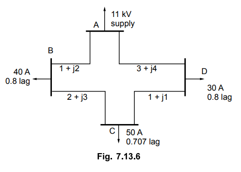
Example 7.13.3
A 3 phase ring distribution ABCD fed at A at 11 kV supplies balanced loads
of 40 A at 0.8 p.f. lagging at B, 50 A at 0.707 p.f. lagging at C and 30 A at
0.8 p.f. lagging at D. The load currents are referred to the supply voltage at
A.
The impedance per phase of the various
sections are,
Section AB = (1 + j2) Ω
Section CD = (1 + j1) Ω
Section BC = (2 + j3) Ω
Section DA = (3+ j4) Ω
Calculate the currents in various
sections and station bus bar voltages at B, C and D.
Solution:
The ring distributor ABCD
is shown in the Fig. 7.13.6. One phase
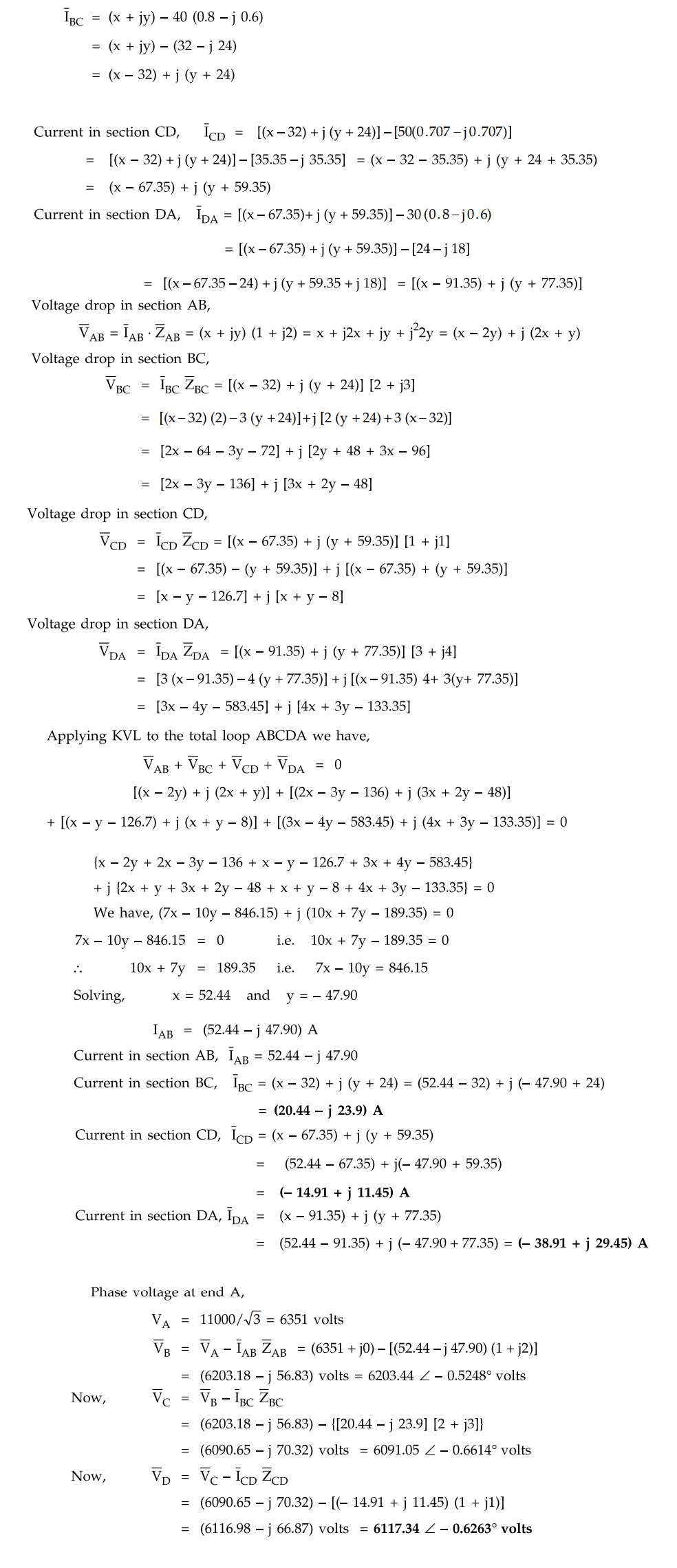
of ring main is shown. The problem can be solved using Kirchhoff's laws. Let
current in section AB be (x + jy).
Current in section BC,
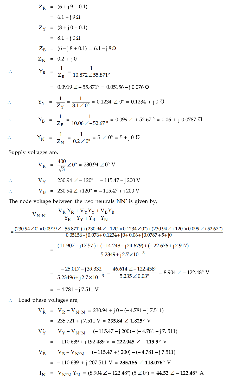
Example 7.13.4
A 400 V, 3 phase 4 wire service mains supplies a star connected load. The
resistance of each line is 0.1 ohm and that of the neutral 0.2 ohm. The load
impedances are ZR = (6 + j 9), Zy = 8 ohms and ZB = (6 - j 8). Calculate the
violtage across each load impedance and current in the neutral. Phase sequence
RYB.
Solution :
The arrangement is shown Fig. 7.13.7.

Total line impedances are,
Review Questions
1. Draw and explain the phasor diagram for an a.c.
distributor with power factors referred to the receiving end voltage.
2. Draw and explain the phasor diagram for an a.c.
distributor with power factors referred to the respective load voltages.
3. A single phase a.c. distributor AB has length cf 300 m
and is fed from end A and is loaded as under :
i) 100 A at 0.707 pf. lagging 200 m from point A
ii) 200 A at 0.8 p.f. lagging 300 m from point A
The total resistance and reactance of the distributor is
0.2 Ω and 0.1 Ω per kilometer. Calculate the voltage drop in the distributor.
The load power factors refer to the voltage at the far end.
[Ans.: 17.44 - j 3.81 volts]
4. A3 phase 400 V distributor AB is loaded as shown in the
Fig. 7.13.8. The3 phase load at point C takes 5 A per phase at a p.f. of 0.8
lagging. At point B, a 3 phase 400 V induction motor is connected which has an
output of 10 HP with an efficiency of 90 % and p.f. 0.85 lagging.
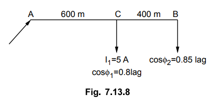
If voltage at point B is to be maintained at 400 V what
should be the voltage at point A ? The resistance and the reactance of the line
are 1 Ω and 0.5 Ω per phase per km
respectively.
[Ans.: 433 volts]
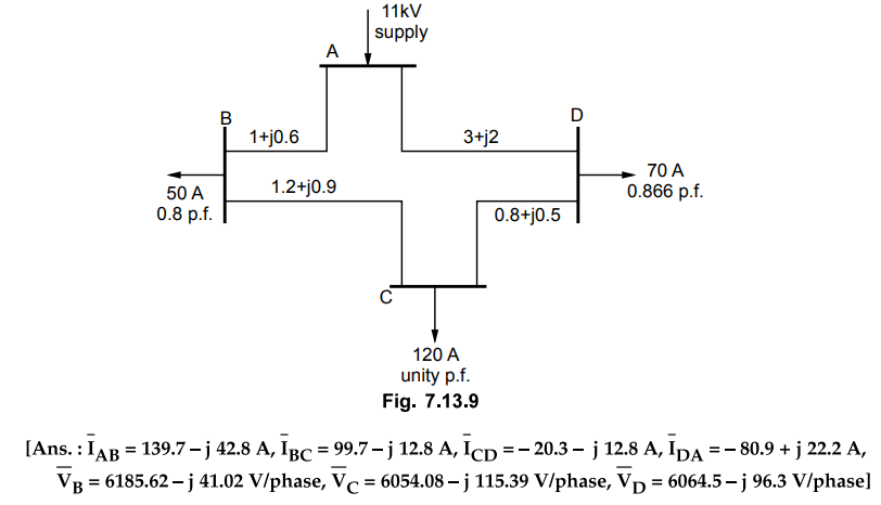
5. A 3 phase ring main ABCD fed at 11 kV is loaded at
points B, C, D as shown in the Fig. 7.13.9. Calculate the currents in various
sections and voltages at B, C and D.
Transmission and Distribution: Unit V: (a) Distribution Systems : Tag: : Calculations - Methods of Solving - Power Factors Referred to Respective Load Voltages - A.C. Distribution
Related Topics
Related Subjects

Transmission and Distribution
EE3401 TD 4th Semester EEE Dept | 2021 Regulation | 4th Semester EEE Dept 2021 Regulation