Electrical Machines II: UNIT I: c. Synchronization and Parallel Operation of Alternators
Alternator On Load
Consider again two alternators running in parallel with each alternator supplying one half of active power and one half of reactive power.
Alternator On Load
Consider
again two alternators running in parallel with each alternator supplying one
half of active power and one half of reactive power. Each alternator supplies a
load current of I such that total load current is 21. It is assumed that E1 =
E2 while the operating power factor is cos and terminal voltage V. The power
triangles for both the alternators can be represented as shown in Fig. 3.14.3
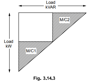
where
both active and reactive powers divided equally giving apparent power triangles
same.
If
now excitation to alternator no. 1 is increased then its induced e.m.f. E1
will increase which will raise the terminal voltage 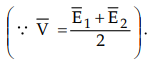 . Now the
difference in induced e.m.f.s will set up a circulating current ISY
= E1 – E2 / 2Z that flows in local circuit. This current
is superimposed on original current distribution.
. Now the
difference in induced e.m.f.s will set up a circulating current ISY
= E1 – E2 / 2Z that flows in local circuit. This current
is superimposed on original current distribution.
From
the circuit diagram it can be seen that current ISY is vectorially added to the
load current of alternator no. 1 and subtracted from the load current of
alternator no. 2. Now the load currents will be changed to I1 and I2
with change in power factors. The new power factors are cos and cos ϕ1.
This is shown in the Fig. 3.14.4.

It
can be seen from the Fig. 3.14.4 that cos ϕ1 is reduced whereas cos ϕ2
is increased. The armature currents for the two machines are changed but their
active components are not changed. Thus changes in kW loading of the two
alternators is negligible but reactive power kVAR1 from first
alternator is increased whereas kVAR2 supplied by second alternator is
decreased which can be seen from power triangles.
3. Phasor Diagram
The
effect of change in excitation on the performance of the two alternators can be
explained with the help of phasor diagram shown in the Fig. 3.14.5.

Again
the two alternators are working in parallel. If now excitation of alternator 1
is increased so that its induced e.m.f. E1 is increased to E1
which will try to increase the terminal voltage V. But the terminal voltage V
can be kept constant by decreasing the excitation of other alternator. The
increase in E1 and decrease in E2 are adjusted in such a way that E
sin 8 remains constant. The difference between E1 and E2
will give rise to circulating current ISY. This current must be added
to I1 and subtracted from I2 which will give new armature
currents I1 and I2
Induced
e.m.f. are given by,

It
can be seen that there is increase in magnitude of I1 but its active
component I1 cos ϕ1 is unaltered. Similarly I2
is decreased in magnitude but its active component I2 cos ϕ2
is unaffected. Thus the load current, terminal voltage and load power factors
are unchanged.
From
the Fig. 3.14.5 it is clear that the alternator 1 operates at a poor p.f. which
delivers greater reactive power than alternator 2 operating at a better p.f.
Since the mechanical power input to the two alternators is not disturbed, the
active power output is remaining same. Thus change in excitation causes only
the kVAR sharing of the two alternators without disturbing kW sharing of the
two machines.
Thus
the load current, the load terminal voltage and the load power factor remain
unchanged but armature currents, induced e.m.f.s and operating power factors
for each of the alternator is changed.
Key Point By varying the
field excitation with the help of rheostats the distribution of reactive power
shared by the alternators and their terminal voltage can be controlled.
4. Division of Load between Two Alternators
The
division of load between the two alternators can be calculated as follows.
From the Fig. 3.14.6 it can also be seen that

Substituting
the above values in equation (3.14.1)
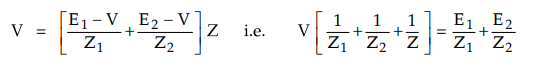
From
the Fig. 3.14.6 it can also be seen that

Subtracting above two equations,

Substituting this value in equation,

Key Point When two e.m.f.s
are unequal in magnitude the second term of above equation represents the
circulating current under loaded conditions.
At
no load (i.e. Z = ∞ ) the circulating current is given by,
ISY
= E1 – E2 / Z1 + Z2
This
expression is already derived in previous section.
Review Question
1. Explain the effect of change in excitation on the load
sharing of two alternators running in parallel. AU : May-04, Marks 6
Electrical Machines II: UNIT I: c. Synchronization and Parallel Operation of Alternators : Tag: Engineering Electrical Machines - II : - Alternator On Load
Related Topics
Related Subjects

Electrical Machines II
EE3405 Machine 2 EM 2 4th Semester EEE Dept | 2021 Regulation | 4th Semester EEE Dept 2021 Regulation