Electrical Machines II: UNIT I: c. Synchronization and Parallel Operation of Alternators
Alternators Connected to Infinite Bus Bar
When two alternators are connected in parallel we have seen that a change in the excitation changes the terminal voltage and p.f. is determined by load.
Alternators Connected to Infinite Bus Bar
We
have already seen that synchronous generators do not operate individually in a
generating station but they are interconnected so that total generating
capacity will be high. When number of alternators are interconnected forming a
system which may be treated as an infinite bus. Infinite bus bar is one which
keeps constant voltage and frequency although the load varies. Thus it may
behave like a voltage source with zero internal impedance and infinite
rotational inertia. Any alternator switched on to or off, the infinite bus does
not cause any change in the voltage and frequency of the system.
The
characteristics of a synchronous generator on infinite bus bars are quite
different from those when it is connected to another alternator and both are in
parallel. When two alternators are connected in parallel we have seen that a
change in the excitation changes the terminal voltage and p.f. is determined by
load. However change in excitation for an alternator connected to infinite bus
bar will not change the terminal voltage but the power factor only is affected
whereas the power developed by an alternator depends only on mechanical power
input.
Now
we will consider the effect of excitation and driving torque on the performance
of an alternator which is connected to infinite bus bar. In all the further
discussion we will take zero losses for the machine.
1. Effect of Excitation
Let
us consider the cylindrical rotor alternator as shown in Fig. 3.16.1 connected
to infinite busbar.
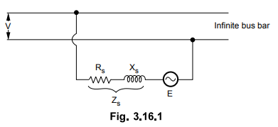
The
voltage equation can be written as

where E = Induced e.m.f. or excitation
e.m.f.
V
= Constant bus voltage
I
- Armature current
Zs
- Synchronous impedance
The
same equation neglecting the armature resistance can be rewritten as,

Again
we will consider the two cases one with alternator on no load and other with
alternator on load.
a.
Alternator on No Load
Since
we are considering the losses to be zero the power angle δ will be zero. Thus the
power transferred from or to the bus is zero

Now
if the excitation is properly adjusted at no load then induced e.m.f. E will be
equal to bus voltage V and no current will flow. This is shown in Fig. 3.16.2.
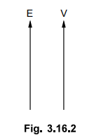
This
is floating condition of alternator.
Now
if the alternator is under excited then induced e.m.f. E will be less than V.
This will cause circulating current IgY to flow which will lead E by angle of
90°. Due to this it produces magnetizing m.m.f. which will try to increase
field m.m.f. to maintain alternator terminal voltage equal to the bus bar
voltage. This is shown in following Fig. 3.16.3.
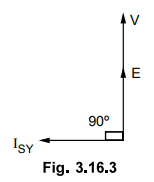
Similarly
if alternator is over excited then induced e.m.f. E will be more than V which
will again cause a circulating current ISY to flow. The power angle δ
is zero. This current lags E by 90o. This will produce demagnetizing
armature m.m.f. which will counterbalance the effect of increased field m.m.f
and again the terminal voltage of an alternator will be equal to constant bus
bar voltage V. This is represented in Fig. 3.16.4

It
can be seen that in both the cases considered above, no active power is
delivered since ISY is in quadrature with V and load angle δ is also
zero. But alternator takes reactive power from bus since E < V and delivers
it to bus if E > V.
b.
Alternator on Load
Now
let us consider that alternator is supplying power to an infinite bus which has
induced e.m.f. E, power angle δ and working at unity power factor with current
I.
With
mechanical power input to the alternator remaining constant, the power given by
EV /Xs sin δ will remain constant. If by varying excitation induced
e.m.f. E is increased to E1 then the load angle will also change from
δ to δ1. From the phasor diagram it can be determined as E1
sin δ1 = E sin δ as V and Xs are constant. The drop due
to synchronous reactance also increases and armature current increases from I
to I1. This current has two components one real component and other
quadrature component. This quadrature component is nothing but demagnetizing
component. This will result in lagging power factor cos ϕ1
Similarly
if the excitation is decreased so that induced e.m.f. reduces from E to E2
with corresponding change in power angle from δ to δ2. The armature
current in this case will be I2 which has real component and
magnetizing component which results in leading power factor cos ϕ2 .
This can be represented in the phasor diagram shown in Fig. 3.16.5.
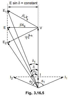
From
the phasor diagram it can be seen that
I1
cos ϕ1 = I2 cos ϕ2 = I
Multiplying
by V throughout,
V
I1 cos ϕ1 = V I2 cos ϕ2 = V I
This
indicates that power delivered to the bus will remain constant. Thus by
changing the field excitation the active power is unaltered. But change in
excitation results in corresponding operating power factor as shown in phasor
diagram.
Key Point : An under excited
alternator operates at leading power factor whereas an over excited alternator
operates at lagging power factor.
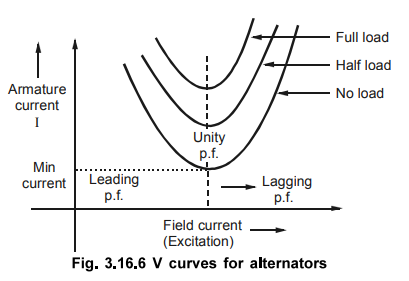
It
can also be seen that armature current is minimum at unity power factor. For
over excited alternator as E1 cos δ > V therefore as seen from case (i) i.e.
no load condition alternator delivers reactive power to the bus where as for
underexcited alternator E2 cos δ < V, alternator takes reactive power from the bus. This
variation of excitation and armature current can be plotted as shown in Fig.
3.16.6. This is known as V curves for synchronous generators by virtue of their
shape.
2. Effect of Driving Torque
As
already discussed in the previous section the driving torque of an alternator
can be changed by throttle opening in steam power plants and by gate opening in
case of hydrogeneration. Let us see the effect of driving torque on performance
of alternator with the help of phasor diagram as shown in Fig. 3.16.7.

The
voltage equation remains same as

The
load angle is δ. Now if the driving torque of alternator is increased keeping excitation
constant then output EV / Xs sin δ also increases as δ is changing,
but E, V and Xs are constant. The angle δ increases so as to balance
between increased mechanical input and the power EV / Xs sin δ . Thus the tip of
phase E follows a curved path. The maximum value of δ will be 90° for which
armature current is I1 leading the bus bar voltage V by power factor
angle ϕ1.
Thus
with increase in input the alternator delivers more power to infinite bus. The
frequency and terminal voltage of an alternator remains same as it is connected
to infinite bus bar.
If
driving torque is decreased, the power angle δ must decrease correspondingly.
If it becomes zero, no power is transferred to the infinite bus. The prime
mover will only supply the losses.
If
driving torque is reversed or if the prime mover is decoupled from the shaft E
shifts and lags behind V, then 8 will be reversed and the operation of machine
will change from synchronous generator to synchronous motor as now  . The synchronous motor operates at a leading p.f. indicating that it is
delivering reactive power to infinite bus.
. The synchronous motor operates at a leading p.f. indicating that it is
delivering reactive power to infinite bus.

Example
: A 3 phase, 11 kV, 2 MV A, turbo alternator is
delivering full load at 0.8 pf lagging. It has a synchronous reactance of 20 %
and the resistance is negligible. If the excitation is increased by 25 %
keeping the input power constant, calculate the new current and the
powerfactor. The machine is connected to infinite bus bars.
Solution
:

Example
for Practice
Example
3.16.2 A 6600 V, 1200 kVA, 3-phase alternator is
delivering full-load at 0.8 p.f. lagging. Its reactance is 25 % and resistance
negligible. By changing the excitation, the e.m.f. is increased by 30 % at this
load. Calculate the new values of current and power factor. The machine is
connected to infinite busbars.
[Ans.:
0.3687 lagging, Ia2 = 227.758 A]
Reivew Question
1. Explain the effect of change in excitation and driving torque
on an alternator connected to infinite bus bar.
Electrical Machines II: UNIT I: c. Synchronization and Parallel Operation of Alternators : Tag: Engineering Electrical Machines - II : - Alternators Connected to Infinite Bus Bar
Related Topics
Related Subjects

Electrical Machines II
EE3405 Machine 2 EM 2 4th Semester EEE Dept | 2021 Regulation | 4th Semester EEE Dept 2021 Regulation