Digital Logic Circuits: Unit III: (b) Analysis & Design of Synchronous Sequential Circuits
Analysis of Clocked Sequential Circuits
• The behaviour of a sequential network is determined from the inputs, the outputs, and the states of its flip-flops. Both the outputs and the next state are function of the inputs and the present state (in case of Moore circuits the outputs are function of only present state).
Analysis of Clocked Sequential Circuits
•
The behaviour of a sequential network is determined from the inputs, the
outputs, and the states of its flip-flops. Both the outputs and the next state
are function of the inputs and the present state (in case of Moore circuits the
outputs are function of only present state). The analysis of sequential circuit
consists of obtaining a table or a diagram for the time sequence of inputs,
outputs and internal states. The success of analysis or design of sequential
network depends largely on the aids and systematic techniques such as
transition tables, state tables, state diagrams and state equations used in
these processes.
•
Consider the sequential circuit to be analysed as shown in Fig. 5.3.1.

•
Let us see the steps to analyze the given synchronous sequential circuit.
•
l. Determine the flip-flop input equations and the output equations from the
sequential circuit.
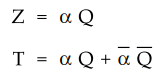
2.
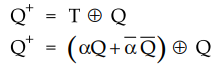
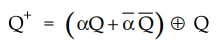
Derive the transition equation.
The
transition equation for T flip-flop is
3.
Plot the next step map for each flip-flop
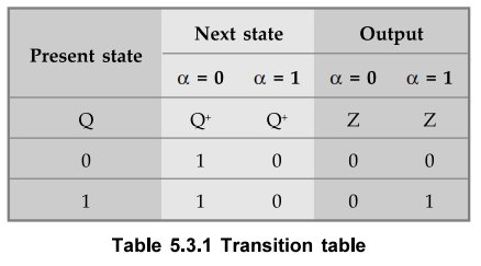
4.
Plot the transition table
Note
:
If circuit consists of more than one flip-flop we have to combine the map of
flip-flop to derive the transition table. (Refer next example)
5.
Draw the state table
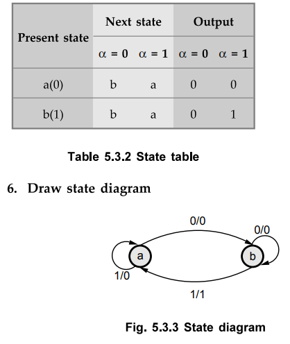
The
transition table shown in Table 5.3.1 can be converted into state table as
shown in Table 5.3.2. Here, new symbols to binary codes are assigned. They are
a = 0, b = 1.

Examples
for Understanding
Ex.
5.3.1 Construct the transition table, state table and state diagram for the
Moore sequential circuit given below
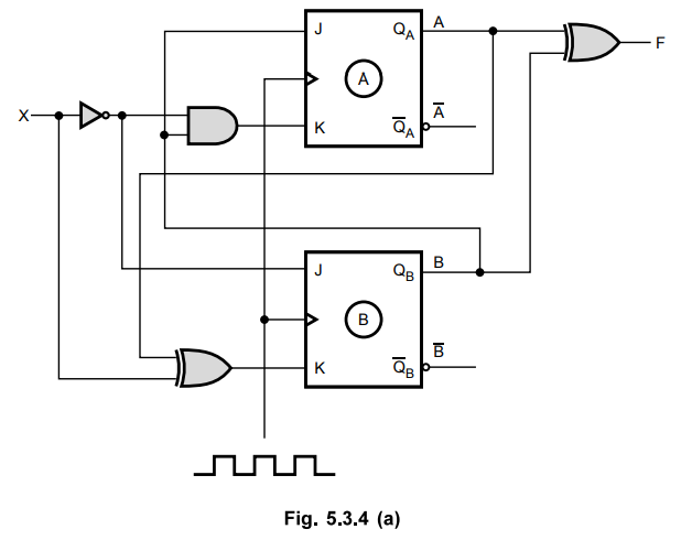
Sol.
:
1.
Determine the flip-flop input equations and the output equations from the
sequential circuit.

2.
Derive the transition equations.
The
transition equations for JK flip-flops can be derived from the characteristic
equation of JK flip-flop as follows :
We
know that for JK flop-flop

3.
Plot a next-state maps for each flip-flop.
The
next-state maps are :

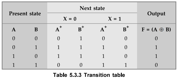
4.
Plot the transition table.
The
transition table can be formed by combining the above two maps. The Table 5.3.3
shows the transition table.
Note
:
For More sequential circuit output only depends on presentstate and not on the
input.
5.
Draw the state table
By
assigning a = 0 0, b = 01, c = 10 and d = 11 we can write state table from the
transition table as shown.

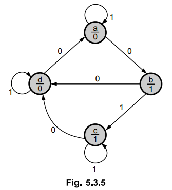
6.
Draw state diagram
From
the state table we can draw state diagram as shown in Fig. 5.3.5.
 Note
:
In case of Moore model, the directed lines are labelled with only one binary
number representing the state of the input that causes the state transition.
The output state is indicated within the circle, below the present state
because output state depends only on present state and not on the input.
Note
:
In case of Moore model, the directed lines are labelled with only one binary
number representing the state of the input that causes the state transition.
The output state is indicated within the circle, below the present state
because output state depends only on present state and not on the input.
Ex.
5.3.2 A sequential circuit with 2D FFs A and B and input X and output Y is
specified by the following next state and output equations.
A(t
+ 1) = AX + BX
B(t
+ 1) = A'X
Y
= (A+B)X'
i)
Draw the logic diagram of the circuit,
ii)
Derive the state table,
iii)
Derive the state diagram.
Sol.
:
i)
Logic diagram

ii)
State table :
Step
1 :
Plot the next-state map for each flip-flop.
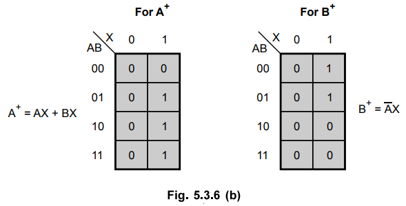
Step
2 :
Plot the transition table.
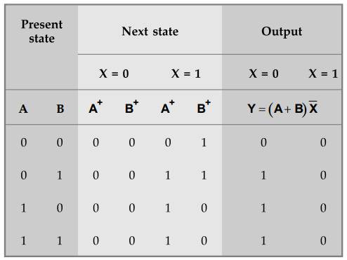
Step
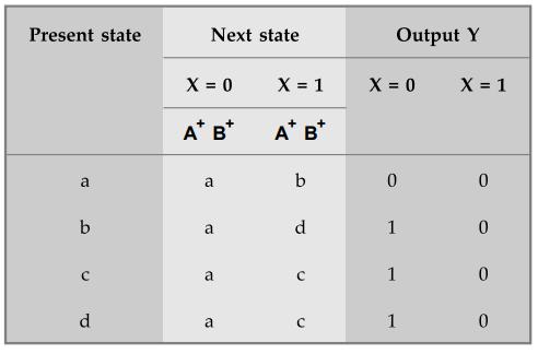
3 :
Draw the state table.
By
assigning a = 00, b = 01, c = 10 and d = 11 we can write state table from the
transition table.
iii)
State diagram

Ex.
5.3.3 A sequential circuit has four FFs ABCD and an input X is described by the
following state equations.
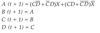
i)
Obtain the sequence of states when X = 1, starting from state ABCD = 0001.
ii)
Obtain the sequence of states when X = 0 starting from state ABCD = 0000.
Sol.
:

Ex.
5.3.4 A sequential circuit has one flip-flop Q, two inputs x and y, and one
output S. It consists of a full adder circuit connected to a D flip-flop, as
shown below. Derive the state table and state diagram of the sequential
circuit.
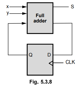
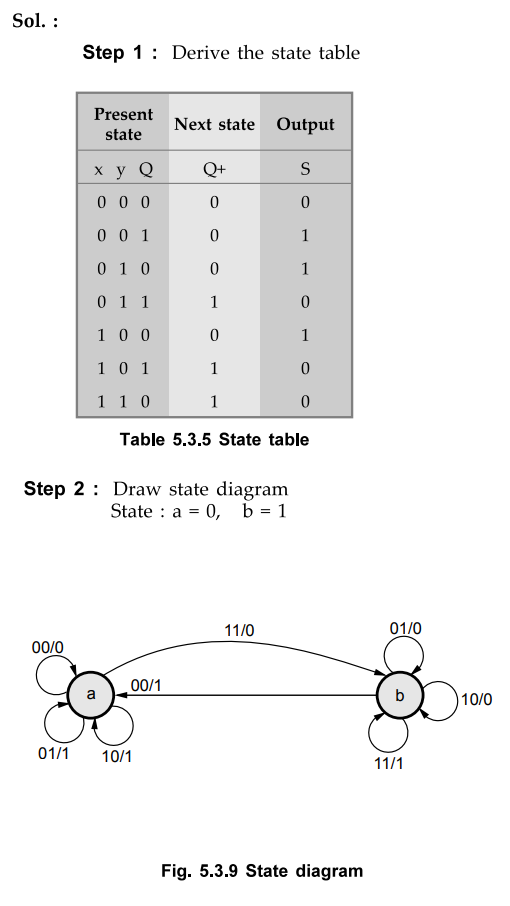
Sol
. :
Examples
for Practice
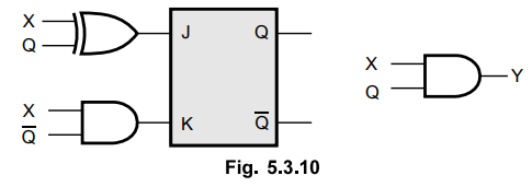
Ex.
5.3.5 Derive the state diagram for the given circuit.
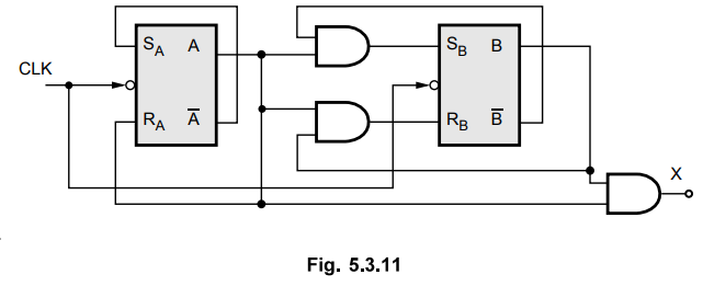
Ex.
5.3.6 Give output function, transition table and state diagram bp analyzing the
sequential circuit shown in Fig. 5.3.11.
Review Question
1. Explain the various steps in the analysis of synchronous
sequential circuits with suitable example.
Digital Logic Circuits: Unit III: (b) Analysis & Design of Synchronous Sequential Circuits : Tag: : - Analysis of Clocked Sequential Circuits
Related Topics
Related Subjects

Digital Logic Circuits
EE3302 3rd Semester EEE Dept | 2021 Regulation | 3rd Semester EEE Dept 2021 Regulation