Digital Logic Circuits: Unit IV: (a) Asynchronous Sequential Circuits
Analysis of Fundamental Mode Sequential Circuits
Asynchronous Sequential Circuits
• Fundamental mode asynchronous sequential circuit analysis requires careful attention because these circuits utilize unclocked memory and level inputs. The procedure to analyze these circuits is as follows :
Analysis of Fundamental Mode Sequential Circuits
AU
: Dec.-10, 11, 12, Hay-12, 13
•
Fundamental mode asynchronous sequential circuit analysis requires careful attention
because these circuits utilize unclocked memory and level inputs. The procedure
to analyze these circuits is as follows :
1.
Determine the next-secondary state and output equations from given sequential
circuit.
2.
Construct the state table.
3.
Construct the transition table.
4.
Construct output map.
Examples
for Understanding
Ex.
7.5.1 Analyze the fundamental mode asynchronous sequential circuit given in
Fig. 7.5.1.

Sol.
:
The given circuit has two input variables and Io and one output variable Z. The
circuit has two feedback paths which provide inputs to the gates, creating
latching operation necessary to produce a sequential circuit. The feedback path
also generates the state variables X0 and X1 The next
state for the circuit is determined by both, the state of input variables and
the state variables.
Step
1 :
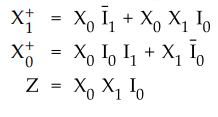
Determine next-secondary state and output equations.
From
the given sequential circuit we can have next-secondary state and output
equations as follows
Step
2 :
Construct state table.
•
From these next-secondary state and output equations we can construct the state
table indicating present-total state, next-total state, stability of the
next-secondary state and the output. The next-secondary state values are found
by assigning present-total state values to the Boolean variables in the next-secondary
state equations to determine X+1 and X+0
•
For the given input and secondary state if next-secondary state does not change
then the state is said to be stable.

Note
:
The shaded portions show that for given inputs, next-secondary states do not
match with the corresponding secondary states and hence they are unstable
states.
The
Fig. 7.5.2 shows the transition table. The numbers written in the table
represent next-secondary state values for particular secondary state and
inputs.

The
circle around next-secondary state value indicate that the state is stable. The
arrows indicate transitions from unstable states to stable states. For example,
if the state (X1 X0, I1 I0) is
1010, the state value is 01 and it is unstable state. The next-secondary stable
state will be 0010 as indicated by arrow. There is no stable state for input I1
I0 = 00 with secondary states 10 and 01.

Ex.
7.5.2 An asynchronous sequential circuit is described by the following
excitation and output function.
Y
= X1X2 + (X1X2) Y, Z = Y
i)
Draw the logic diagram of the circuit.
ii)
Derive the transition table and output map.
iii)
Describe the behaviour of the circuit.
Sol.
:
i) The logic diagram is as shown in the Fig. 7.5.4 (a).

iii)
The circuit gives carry output of the full adder circuit.
Ex.
7.5.3 An asynchronous sequential circuit has two internal states and one
output. The excitation and output function describing the circuit are as
follows.
Y1
= x1x2 + x1y2+ x2y1
Y2 = x2 + x1y1y2
+ x1, y1 Z = x2 + y1
Sol.
:
The logic diagram is as shown in the Fig. 7.5.5 (a).


Ex.
7.5.4 Derive the flow table for the circuit given in the Fig. 7.5.6.

Sol.
:
Step
1 :
The excitation and output equations for the given circuit are :

Ex.
7.5.5 Consider the following asynchronous sequential circuit and draw maps,
transition table and state table.
AU
: Dec.-12, May-13, Marks 16

Sol.
:
Considering the excitation variables as outputs and the secondary variables as
inputs we have,

Example
for Practice
Ex.
7.5.6 Analyse the fundamental mode asynchronous sequential circuit shown in Fig.
7.5.10.

Review Questions
1. List and explain the steps used for analyzing an asynchronous
sequential circuit.
AU : Dec.-10, Marks 8
2. State the condition of stability in asynchronous sequential
logic.
3. List and explain the steps used for analyzing an asynchronous
sequential circuit.
AU : May-12, 13, Marks 8
4. When does oscillation occur in an asynchronous sequential
logic circuit ?
Digital Logic Circuits: Unit IV: (a) Asynchronous Sequential Circuits : Tag: : Asynchronous Sequential Circuits - Analysis of Fundamental Mode Sequential Circuits
Related Topics
Related Subjects

Digital Logic Circuits
EE3302 3rd Semester EEE Dept | 2021 Regulation | 3rd Semester EEE Dept 2021 Regulation