Electromagnetic Theory: Unit IV: Time Varying Fields and Maxwells Equations
Applications
Time Varying Fields and Maxwells Equations
1. Transformers 2. Magnetic Brake 3. Induction Heating 4. Magnetic Levitation 5. Electromagnetic Propulsion of Ships and Submarines 6. Electromagnetic Launcher (EML) 7. Electromagnetic Forming 8. Eddy Current Testing of Materials 9. Magnetohydrodynamic (MHD) Generator
Applications
AU
: Dec.-17
1. Transformers
•
A transformer is an a.c. device which is used to transform voltages and
currents and hence the impedance. It is based on the principle of Faraday's
law. The transformer works on the principle of mutual induction. It transfers
electrical energy from one circuit to other eventhough there is no connection
between two circuits.
a.
Principle of Working
•
According to the principle of mutual induction, when two coils are inductively
coupled and if current in one coil is changed uniformly, then e.m.f. gets
induced in other coil. Such induced e.m.f. in coil 2 can drive current when a
closed path is provided to it. The transformer works on the same principle. In
its elementary form it consists of two inductive coils which are electrically
separated but linked through a common magnetic path which is made up of
ferromagnetic material such as iron which gives low reluctance high
permeability magnetic path. The two coils usually have high mutual inductance.
The basic transformer is as shown in the Fig. 9.10.1 (a) and its symbolic
representation is as shown in the Fig. 9.10.1 (b).

•
In general, the core of the transformer is laminated which helps in reducing
induced currents in core and thus it reduces losses due to core current.
Ideal
Transformer
A
transformer is said to be ideal if
i)
It has no losses.
ii)
Its winding have zero resistance (ideal coils).
iii)
The flux produced by primary coil completely links with secondary coil.
iv)
The permeability of core is high such that only negligible current is required
to establish flux in it. Ideally the permeability is ∞.
v) The magnetic path is closed.
•
The flux of magnetic circuit is given by,
ϕ
= ∑ NiIi / ∑ Ɽj
Ni
= Number of turns of ith coil
Ii
= Current in ith coil
Ɽj
= Magnetic reluctance of jth segment of the path
•
But the reluctance of the magnetic path is given by,
Ɽ
= lm / µS
•
where Zm is the length of magnetic path and S is the cross-sectional area of
path. Assuming zero core losses or coil losses, the magnetic flux can be
written as,
ϕ
= N1I1 – N2I2 / Ɽ
•
Negative sign of term N2I2 indicates that I2
is the induced current and it opposes the flux produced I2. Assuming p to be as
the core is made up of high permeability material like iron, then Ɽ → 0.
•
Thus we can write,
N1I1
– N2I2 = ϕ Ɽ ≈ 0
•
This equation is an approximation which holds good for many application and
gives solution almost same as ideal solution.
•
Thus we can write,
N1I1 = N2I2
•
That means the total flux in the core is same in both coils the e.m.fs. can be
expressed as,
V1
= - N1 (d ϕ / dt)
and
V2 = - N2 (d ϕ / dt)
•
From above conditions obtained for voltages and currents, we can write,
V1
/ V2 = I2 / I1 = N1 / N2
= a
•
Where a is known as turns ratio or transformer ratio.
•
By definition, the transformer transforms voltage or current from one circuit
to other circuit. But the transformer can be used to transform impedance of the
circuit. The impedance of primary winding is given by,
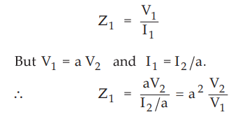
But
V2 / I2 is nothing
but the impedance of secondary
winding,
i.e. Z2
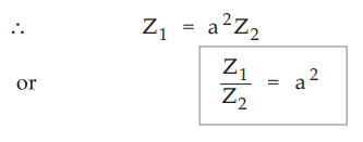
•
Thus transformer can be used for impedance matching by properly adjusting
number of turns.
2. Magnetic Brake
•
The magnetic brake is very useful application of an electromagnetic induction.
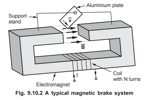
•
Consider an electromagnet which produces magnetic field ![]() in the gap
which is constant throughout. A piece of aluminium or any conducting material
which is flat is placed on electromagnet with support such that the pendulum
like flat piece move easily into the gap. When the current carried by the coil
of electromagnet is zero (i.e. I = 0), the oscillations of flat piece are not
affected. But when the current flows through the coil of an electromagnet, the
magnetic field is developed in the gap.
As a flat piece of conducting material oscillates i.e. moves in a constant
magnetic field
in the gap
which is constant throughout. A piece of aluminium or any conducting material
which is flat is placed on electromagnet with support such that the pendulum
like flat piece move easily into the gap. When the current carried by the coil
of electromagnet is zero (i.e. I = 0), the oscillations of flat piece are not
affected. But when the current flows through the coil of an electromagnet, the
magnetic field is developed in the gap.
As a flat piece of conducting material oscillates i.e. moves in a constant
magnetic field ![]() , the current is generated into flat plate. This
current opposes the cause producing it i.e.
, the current is generated into flat plate. This
current opposes the cause producing it i.e. ![]() according to Lenz's law.
The induced current continues to oppose the flux density
according to Lenz's law.
The induced current continues to oppose the flux density ![]() maintaining
conditions as shown in the Fig. 9.10.3.
maintaining
conditions as shown in the Fig. 9.10.3.

•
The magnitude of the induced current depends on the velocity with which the
plate penetrates into the gap of an electromagnet. The relative directions of
velocity of plate, magnetic field and current are as shown in the Fig. 9.10.4.
•
The volumetric force density is given by,
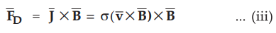
•
As all vectors are perpendicular to each other, over volume V the total force
is given by,
F
= σvB2V ... (iv)
•
The direction of this force is opposite to ![]() This force damps the
oscillations of plate into the gap. With the finite conductivity |σ of the
plate material, the power due to the induced current gets dissipated in plate
itself and thus effectively the plate deaccelerates. This process continues
till the plate attains a static state of equilibrium into the gap and stops
oscillating completely.
This force damps the
oscillations of plate into the gap. With the finite conductivity |σ of the
plate material, the power due to the induced current gets dissipated in plate
itself and thus effectively the plate deaccelerates. This process continues
till the plate attains a static state of equilibrium into the gap and stops
oscillating completely.
•
The principle of magnetic brake is used in vehicles such as trucks. A practical
magnetic brake used in vehicle is as shown in the Fig. 9.10.5.
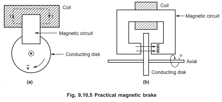
•
A conducting circular disk is mounted on the axial at vehicle. An electromagnet
is placed near disk such that the disk can move in the gap of electromagnet.
•
During application of a mechanical brake, current is applied to the
electromagnet also. Because of this alongwith mechanical brake effect, the
effect of magnetic brake is also observed. But the braking effect assumes
velocity ![]() Thus a vehicle cannot be completely stopped using electromagnetic
brake. Thus it is also called magnetic damper or magnetic retarder.
Thus a vehicle cannot be completely stopped using electromagnetic
brake. Thus it is also called magnetic damper or magnetic retarder.
3. Induction Heating
•
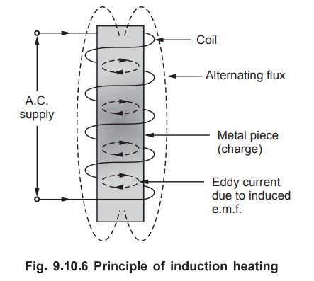
The heating method is based on the principle of electromagnetic induction. When
alternating current flows in a conductor it produces alternating flux. If any
other conducting material is placed in this magnetic flux which is alternating,
the e.m.f. gets induced in the conducting material. This induced e.m.f. drives
eddy currents in that piece. The power loss due to such eddy currents appears
as heat. The action of inducing e.m.f. in other material due to alternating
flux produced by a current carrying conductor is a transformer action.
Key
Point : The only difference between transformer and
induction heating is a transformer electrical energy available in secondary is utilised
outside secondary while in induction it is used to heat the charge itself which
acts as a short circuited secondary.
•
The Fig. 9.10.6 shows the principle of induction heating.
•
The heating effect due to such principle depends on following factors :
1.
It is proportional to relative permeability. So heating produced in magnetic
material is more than non magnetic material. In addition to the eddy currents,
there is loss due to hysteresis in magnetic material which contributes to
generate more heat. But hysteresis loss becomes negligible at high frequencies.
2.
For a given material and supply frequency, heating is proportional to
magnetomotive force (m.m.f.). The force can be varied either by changing
current or by varying number of turns of coil as m.m.f. is NI.
3.
For a given material and magnetising force, heating effect can be increased by
employing high frequency supply.
Induction
heating can be also classified as,
i)
Direct induction heating :
In
this, currents are induced in the charge itself. This is usually used in
furnaces for smelting (extraction of metal from ore), melting of metals etc.
This requires very high frequency supply. These are further classified as core
type and coreless type direct induction furnaces.
ii)
Indirect induction heating :
In
this method, eddy currents are induced in the heating element. Thus heat
produced by heating element is then transferred to the charge by radiation or
convection.
4. Magnetic Levitation
•
A magnetic levitation is a method by which an object is suspended without any
support other than magnetic fields. It is thus also known as magnetic
suspension or simply maglev.
•
The basic principle behind a magnetic levitation is that the opposite poles of
magnets attract each other while like poles repel each other. The object is
said to be under magnetic levitation when the object floats because of the
repelling quality of magnets. So when the force generated by the
electromagnetic repulsion is sufficiently strong such that the weight of the
object is balanced, then that object is under magnetic levitation. The effects
of gravitation acceleration and all other accelerations are counter-acted by
mangetic pressure.
•
The magnetic materials and the system are capable of attracting or pressing
each other (towards each other or away from each other) because of a force
which depends on the magnetic field and area of magnets. As discussed earlier,
the magnetic pressure counteracts the gravitational acceleration, we can define
magnetic pressure mathematically as follows.
Pmag
= B2 / 2 µ0
where Pmag = Magnetic pressure
which is magnetic force per unit area and it is measured in pascles.
B
= Magnetic field measured in tesla
µ0
= Permeability of vacuum
=
4 π
× 10-7 N/A2
a.
Methods for Obtaining Magnetic Levitation
•
In general there are various methods for obtaining magnetic levitation. It is
proved that to levitate stably against gravity only static magnetism is not
sufficient. But it should be accomplished with use of diamagnetic materials, servomechanisms,
superconductors and systems with eddy currents. The diamagnetic substances
repel the magnetic field. This effect can be used for levitation of light
objects. More perticularly, superconducting substances are perfect diamagnetic
substances which can lift heavier weight objects. Some of the important methods
to obtain magnetic levitation are as follows.
1.
Mechanical constraint (pseudo levitation)
•
In mechanical constraint levitation, the main lifting force is provided by the
magnetic levitation but the stability is provided by a mechanical bearing which
bears little load. This is called pseudo levitation.
•
In this type of levitation two magnets are mechanically constrained along a
single axis and arranged such that they strongly repel each other. This
effectively levitates one of the magnets above other. If in case the two
magnets are attracted towards each other, then the magnets are constrained
using a tensile member like string or cable from touching each other.
2. Direct diamagnetic levitation
• A diamagnetic substance repel magnetic field. Actually all materials have diamagnetic properties but the effect is very weak. Also these properties are overcome by the paramagnetic or ferromagnetic properties of the object. Thus any material, in which diamagnetic component is strongest, will be repeled by a magnet eventhough the repulsive force is not strong enough.
The
minimum criterion for the diamagnetic levitation is given by,
B
(dB / dz) = µ0ρ g/ χ
where B = Magnetic field
dB
/ dz = Rate of change of magnetic field along vertical i.e. z-axis.
µ0
= Permeability of vacuum or free
space
= 4 π
× 10-7 N/A2
ρ
= Density of material
g
= Gravitational force
χ
= Magnetic susceptibility
•
Practically the diamagnatic levitation is used to levitate light weight pieces
of graphite or bismuth above strong permanent magnet. Water being diamagnetic
in nature, the diamagnetic levitation can be used very effectively to levitate
water droplets. The main drawback of direct diamagnetic levitation is that very
high magnetic fields are required. The typical range of required magnetic field
is 12 to 16 tesla. This creats serious problems in ferromagnetic materials
present nearby.
•
Under ideal conditions, along vertical axis, the water levitates at 1400 T2/m
while graphite levitates at 375 T2 / m
3.
Superconductors
•
Basically superconductors are perfect diamagnets with µr = 0. The
superconductors have unique property of completely expelling magnetic fields
due to Meissner effect during formation of superconductivity in initial stages.
In the levitation system using superconductors, the magnet is stabilized
because of the flux pinning within the superconductor itself. This stops the
superconductor from leaving the magnetic field. This principle is used in
Electrodynamic Suspension (EDS) systems, superconducting bearings, flywheels.
4.
Servomechanisms
•
The force of magnet decreases with increasing distances and increases for
closer distances. But this is unstable condition. For stable operation, the
object should be placed at stable position always. In case there is variation
from a stable position, then it should be pushed back to the target position.
For this certain corrective action is necessary.
•
To achieve stable magnetic levitation, the position and the speed of an object
being levited is measured. By using feedback loop, the corrective action
adjusts one or more electromagnets to locate object at a target position by
correcting speed of the object. This forms a servomechanism.
•
In most of the magnetic levitation systems, magnetic attraction is used for
pulling object upwards against gravity. But some of the systems, use
combination of magnetic attraction and magnetic repulsion to push object
upwards. The systems with such combinations are called Electromagnetic
Suspension (EMS) Systems.
•
The basic principle is that the electromagnet placed above the object being
levited is turned off when the object gets closer while it is turned on when
the object falls away from the target position. The example of an application
based on EMS system is magnetic levitation trains (commonly called Maglevs).
The train wraps around the track and the train is pulled upwards against
gravity using very strong magnetic fields. Using effective servo controls, the
train is safely kept at a constant distance from the track. It is illustrated
in the Fig. 9.10.7.

5. Electromagnetic Propulsion of Ships and Submarines
•
An electromagnetic propulsion is a process of accelerating any object using
utilization of flowing electrical current and magnetic fields. The magnetic
field of opposite type is created by such electrical current. It can also be
utilized for charging of a fluid. When a current flows through conductor placed
in a magnetic field, Lorentz force i.e. electromagnetic force is produced. This
force pushes conductor in a direction perpendicular to direction of current
through conductor and direction of magnetic field. Such an electromangetic
force causes propulsion which is commonly known as Electromagnetic Propulsion
(EMP). Thus propelling of an object using basic concept of electromagnetism is
nothing but electromagnetic propulsion system.
•
The concept of electromagnetic propulsion is very much similar to that of
magnetic launcher commonly called rail gun. For propulsion of ships and
submarines, the rails are submerged into sea water. Now being a conductive in
nature, the sea water makes the space between rails completely conductive in
nature. When the current passes through the sea water, a force is developed on
the sea water. If the magnetic field also exists between the rails submerged,
the sea water is pushed out of the space between rails. The application can be
made more useful by covering rails with non-conductive surface, the water is
expelled as a jet. Similar to the water jet boat, the reaction force moves
water craft forward. This device is useful for submarines as a propulsion
mechanism and it is called magnetohydrodynamic pump.
•
The main advantage of an electromagnetic propulsion is that reduction in the
noise. But the limitations of this process is the requirement of large currents
and reduction in the overall efficiency because of low conductivity of sea
water. The efficiency can be increased by producing very large magnetic fields
with the help of superconducting magnet along with associated cooling
equipment.
•
Using this technique, pumping of molten metals is very easy. In typical nuclear
power plant, pumping of molten sodium is required. This method is found to be
effective as it can be used as pump without moving parts and also all the
metals are highly conductive in nature.
6. Electromagnetic Launcher (EML)
•
An electromagnetic launcher (EML) is the practical application of force exerted
on currents. The electromagnetic launchers are commonly called electromagnetic
rail launchers or rail guns.
•
A typical electromagnetic launcher consists of two parallel rails made up of a
electrically conductive material and are attached with a narrow space between
them to form a barrel. The projectile that is to be propelled from the
electromagnetic launcher is attached to the back of barrel. The projectile is
made up of conducting material so that the rails get started to each other as
shown in the Fig. 9.10.8.
•
Due to the current in rails, magnetic flux density is produced between the
rails as shown in the Fig. 9.10.8 (b). The interaction of current in the
projectile and the field forces the projectile out of rails. The
electromagnetic launchers have capability to a achieve velocities greater than
that attained in thermodynamic guns and explosives for military applications.
With high enough velocities achieved, the electromagnetic launchers are used in
important commercial, military and scientific applications. The EML can be used
to fire satellite into orbit. Using EML much more damage is possible used in
military applications as escape velocities are possible with it. The EML can be
used is scientific applications to accelerate very small masses in area of particle
research. The electromagnetic accelerators designed to launch projectiles at
hypervelocities must be evacuated in order to avoid the unwanted atmospheric
drag effects.
7. Electromagnetic Forming
•
An electromagnetic forming is a process which includes high velocity, cold
forming of electrically conductive metals, like copper and aluminium. This
process is also known as EM forming or Magneforming. The piece of metal can be
reshaped by high intensity pulsed magnetic field which induces a current in the
piece of metal. The repulsive magnetic field is also produced which rapidly
reshapes the portion of the piece of metal. This technique is also known as
high velocity forming.
Principle
of electromagnetic forming
•
The rapidly changing magnetic field around the coil induces a current in a
conductor placed nearby coil according to the principle of electromagnetic
induction. The current flowing through the conductor sets up a corresponding
magnetic field around it. Then according to Lenz's law the magnetic fields
within coil and conductor repel each other strongly.
Operation
•
The piece of metal to be fabricated is placed in the proximity of heavily
constructed coil of wire (which is called work wire) known as forming coil. A
large pulse of current is forced through the forming coil by rapidly
discharging high voltage capacitor bank using switch. In practical process, an
ignition or spark gap is used as switch. This high pulse of current thus in
turn produces a fast oscillating, ultrastrong magnetic field around the forming
coil.
•
When the switch is closed, the capacitor bank discharges electrical energy
stored through the forming coil which produces a rapidly changing magnetic
field. This changing magnetic field induces a current in the piece of metal
placed within forming coil placed in
supporting coil casing. The current flowing in the piece of metal develops a
opposite magnetic field. Correspondingly which rapidly repels the piece of
metal from the forming coil, thus the reshaping of metal piece is done. The
effect of reciprocal forces acting against the forming coil is eliminated by
placing a forming coil inside a supportive coil casing.

Advantages
The
advantages of an electromagnetic forming compared with conventional mechanical
forming are as follows.
i)
The amount of stretch in a conductor without tearing is improved. This property
is called formability of conductor.
ii)
The wrinkling in a metal (or conductor) is supressed considerably.
iii)
This method allows to achieve very close tolerances.
iv)
This method can be carried out using single sided dies, thus tooling cost
reduces.
v)
The process can be carried out in a clean room conditions because lubricants
are not required in this method.
vi)
In this method, a mechanical contact with a metal to be fabricated is not
required. Thus there is no surface contamination and tooling marks observed in
the metal. Thus prior to forming process, finishing of surface can be done.
vii)
The electromagnetic forming can be combined with joining and assembling with
dissimilar components such as glass, plastic, composites, other metals etc.
Disadvantages
The
disadvantages of electromagnetic forming are as follows :
i)
The direct forming of non-conductive metal is not possible. For forming of non-conductive
metals, a conductive drive plate is required.
ii)
The voltages and currents involved are very high. Hence safety considerations
required to be monitored continuously.
iii)
Forming of large sheet metals is not possible as the current in the large coils
is limited.
Applications
•
Basically an electromagnetic forming is used mostly to shrink or expand the
cylindrical tubing. It can also be used to form a sheet metal repeling it onto
a shaped die at very high velocity. Using electromagnetic pulse welding with a
metallurgical weld, a high quality joints can be formed using this method. The
electromagnetic forming is most effective with good conductors such as copper,
aluminium (which are good conductors of electricity) but the process can be
used with some modifications for materials like steel which is a poor conductor
of electricity.
8. Eddy Current Testing of Materials
•
Any conducting material can be tested for any flaw in it using eddy current
testing method. Basically eddy current testing method comes under the class of
non-destructive testing (NDT) which means testing of metallic conductors
without destroying or damaging them. Many times there are defects in a material
which are not visible due to paint or coating covering them. Sometimes there can
be defects in materials which are not visible with human eyes or any visual
method of inspection. In such cases eddy current testing plays very important
role in detecting any such defects.

a.
Basic Principle of Eddy Current Testing
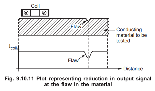
• An eddy current testing is based on the phenomenon of electromagnetic induction. A simple coil is connected to constant a.c. voltage source (or constant current source). When an a.c. current flows through the coil at a perticular frequency, a magnetic field of oscillating type is generated near coil as shown in the Fig. 9.10.10 (a). If the conditions are kept unchanged, the inductance of the coil remains constant. So the equivalent impedance of the circuit also remains constant say Z1 When the coil carrying a.c. constant current and oscillating magnetic field around it is moved closer to the conducting material to be tested, because of induced e.m.f., the induced currents flow through conducting material as shown in the Fig. 9.10.10 (b). As more power is to be delivered by the source, now the impedance of circuit consisting coil decreases to new value Z2. Thus the current in the coil changes for constant a.c. voltage source (or voltage across coil changes for constant a.c. current source). The value of this current flowing through coil (or voltage across coil) is used as a reference reading for current (or voltage) and inturn for impedance. Now suppose there is a flaw or defect in a conducting material as shown in the Fig. 9.10.10 (c).

When the coil and its
magnetic field are brought closer to the conducting material, the flow of
electrons (to be specific circular flow of electrons) called eddy current begin
to move through the conducting material like a flow of swirling water. The eddy
current flowing through conducting material set ups its own magnetic field
which interacts with the magnetic field of coil through mutual inductance. Thus
e.m.f. is induced in conducting material. Now where there is a defect in
material to be tested, the amplitude and also the pattern of eddy current gets
altered. So effectively it alters the resulting magnetic field due to the eddy
current. As a result, movement of electrons in the coil gets affected and this
ends in varying the impedance of coil to new value Z3 with is
obviously different than the reference value of impedance i.e. Z2.
•
Thus by measuring current for constant voltage source (or voltage for constant
current source), we can get the direct information about the condition of
material. Thus the variation in coil impedance directly detects t he defect in
the material.
The
defects in the material to be tested can be
i)
Changes in material conditions such as crack, inclusion, corrosion.
ii)
Changes in material property such as change in conductivity, change in permeability
etc.
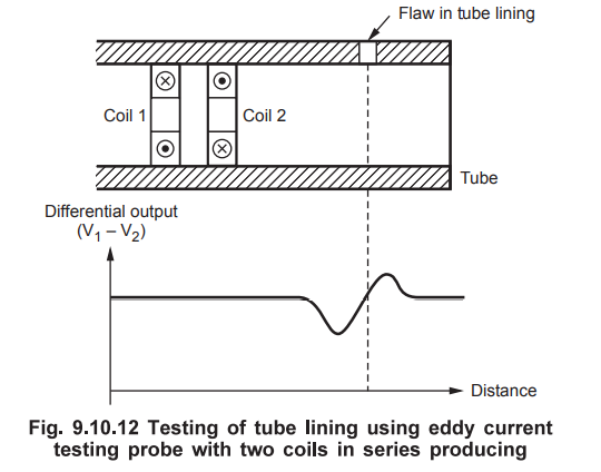
•
Many times, it is necessary to inspect or test tubes of heat exchanger unit and
air conditioning units and power plants. For such testing a special probe is
used. It consists two coils connected in series which provide differential
output as shown in the Fig. 9.10.12.
•
When the probe with two coils move along a material of good condition, the
output is zero. But as probe moves over a defect in material like hole in
material, then the impedance of the coil over a defect shows different
impedance as compared with other coil which is over portion of good condition
material and thus non-zero is obtained as shown in the Fig. 9.10.12.
b.
Factors Affecting Eddy Current Testing
•
There are number of factors affecting the operation of eddy current testing.
The eddy currents in materials with higher conductivity are more sensitive to
the surface defects but will be less penetrating into the material. Basically
penetration also depends on the test frequency of the input signal. Higher
frequency test signals increase surface resolution but limit the depth of
penetration. On the other hand, signals with low frequencies penetrate at
greater depth. The large coils are capable of inspecting greater volume of
material. But smaller coils are most sensitive to the small defects near
surface as compared with larger coils. With the variation in permeability of
material, there is a possibility of generation of noise which limits
resolution. The basic properties of material like permeability, conductivity
are beyond control, the selection of test frequency, coil type and coil size is
done on the basis of test requirements.
9. Magnetohydrodynamic (MHD) Generator
•
The magnetohydrodynamic (MHD) generator is a device used to generate
electricity or electrical energy. The MHD generators are similar to the
conventional electric generators. But conventional electric generators use
solid conductors to generate electric power while the MHD generators use
electrically conducting fluid. A typical setup of a MHD generator is as shown
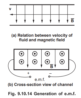
in the Fig. 9.10.13.

•
Under high pressure, an electrically conducting fluid is passed through the
magnetic channel formed between the conducting electrodes with very high speed.
A strong magnetic field is produced in a channel formed by electrodes using
superconducting magnets. The magnetic field inside the channel is usually about
3 to 5 tesla. The two electrodes are placed right angles to each other and are
isolated from the magnets. When the conducting fluid is passed through the
channel, the fluid experiences an electromotive force. According to the
Faraday's law of electromagnetic induction, e.m.f. is induced in a coil
whenever there is a change in magnetic flux linked with the coil. Note that the
electromagnets are stationary but the conducting fluid is moving. This causes
generation of electricity. The relation between the velocity of conducting
fluid and the magnetic fluid is as shown in the Fig. 9.10.14 (a). This clearly
indicates that the right plate becomes negative while the left plate becomes
positive as shown in the Fig. 9.10.14 (b).
•
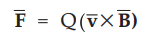
The MHD generator works on the principle of Lorentz force law given by,
•
The direction of motion of fluid is dependent on the direction of the magnetic
field.
•
Generally, the conducting fluids used in MHD generator are plasma and sea or
salt water. In most of the MHD generators use highly ionized gases which are
produced by burning fossil fuels. The conductivity of the ionized gases can be
increased by adding conducting ions such as alkali metal vapours. This is
called seeding of ionized gases. In case of a coal fired MHD generator, using
potassium carbonate as a seed, the conductivity of the gas can be increased
considerably.
•
The MHD generators produce d.c. directly hence they are also called
magnetohydrodynamic d.c. generators. The important point is that these
generators are stationary. In case of rotating generators a.c. is produced than
d.c. Inspite of having very low efficiency (less than 15 %), these generators
are popular because they operate in closed circuits and the system is fully
contained. But practically, these generator are hard to handle as the system
needs very high magnetic fields, high pressures, temperatures to be maintained
in the channel.
The
MHD generators can be constructed in various designs such as Faraday generator,
Hall generator, disc generator etc. The Faraday generator was the first MHD
generator made by Micheal Faraday in 1831. The Faraday generator uses copper
discs and horse shoe magnets to generate electricity.
Review Questions
1. Explain principle induction heating.
2. Describe the function of a transformer starting from
fundamental principles.
3. Explain electromagnetic propulsion of ships and submarines.
4. Write a note on electromagnetic launcher.
5. Explain briefly electromagnetic forming. Write its
advantages, disadvantages and applications.
6. Explain basic principle of operation of eddy current testing
with the help of suitable diagrams.
7. What are the factors affecting eddy current testing ?
8. With the help of suitable diagram explain MHD generator.
9. Describe the applications where circuit theory is used and
applications, where field theory is used.
AU : Dec.-17, Marks 7
Electromagnetic Theory: Unit IV: Time Varying Fields and Maxwells Equations : Tag: : Time Varying Fields and Maxwells Equations - Applications
Related Topics
Related Subjects

Electromagnetic Theory
EE3301 3rd Semester EEE Dept | 2021 Regulation | 3rd Semester EEE Dept 2021 Regulation