Microprocessors and Microcontrollers: Unit IV: (e) Keyboard and Display Controller - 8279
Applications
Keyboard and Display Controller - 8279
In this section we will discuss many useful applications with different modes of keyboard and display interfacing. In addition to this we are going to see the software requirement to control the interfacing circuits.
Applications
In
this section we will discuss many useful applications with different modes of
keyboard and display interfacing. In addition to this we are going to see the
software requirement to control the interfacing circuits. All these
applications are illustrated using different examples.
Lab Experiment 12.9.1 : Hardware and
software for 8x8 keyboard interface using 8279.
Statement :
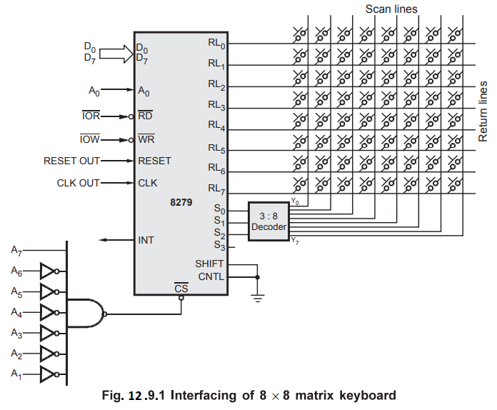
Interface an 8 × 8 matrix keyboard to 8085 through 8279 in 2-key lockout mode
and write an assembly language program to read keycode of the pressed key. The
external clock frequency is 2 MHz. Use I/O mapped I/O technique.
Solution
:
The 8×8 matrix keyboard can be interfaced to 8085 through 8279 in two ways.
1.
Without interrupt signal
2.
With interrupt signal (Interrupt driven Input)
We
will see both the ways one by one.
1.
Without interrupt signal
Hardware
: Fig. 12.9.1 shows the interfacing of 8 × 8 matrix keyboard.
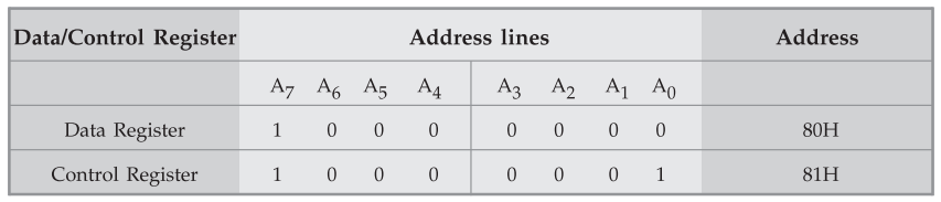
I/O
Map :
Software
:
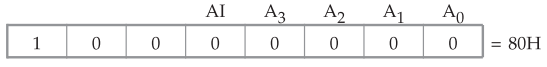
Step
1 : Find
keyboard/display command word. To interface 8x8 matrix keyboard we need 8 scan
lines and 8 return lines. To get 8 scan lines. We have to select encoded scan
keyboard mode. Therefore, the keyboard/display command word for above keyboard
configuration is given as follows :
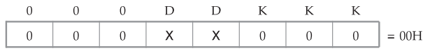
Note
000 → Encoded scan keyboard - 2 key lockout
X
→ don't care
Step
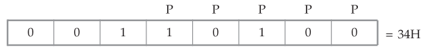
2 :
Find program clock command word
External
clock frequency is 2 MHz
Prescaler
value = 2 MHz / 100kHz
=
20 = (10100)2
Therefore,
the program clock command word is as given below :
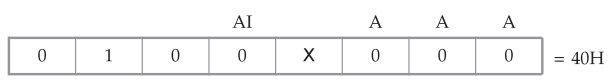
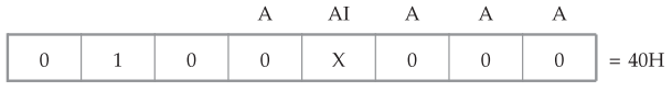
Step
3 :
Find Read FIFO/sensor RAM command word we want to read first entry from the
FIFO RAM. Therefore command word is as given below.
Program
:
MVI
A, 00H
OUT
81H ; Initialize keyboard/display
;
in encoded scan keyboard-2 keylockout mode
MVI
A 34H
OUT
81H ; Initialize prescaler count
BACK
: IN 81H ; Read FIFO status word
ANI
07H ; Mask bit B3 to B7
JZ
BACK ; if 0, key is not pressed wait for
;
key press otherwise read FIFO
;
RAM
MVI
A, 40H ; Initialize 8279 in read
OUT
81H ; FIFO RAM mode
IN
80H ; Read FIFO RAM (keycode)
HLT
; Stop program execution
2.
With interrupt signal
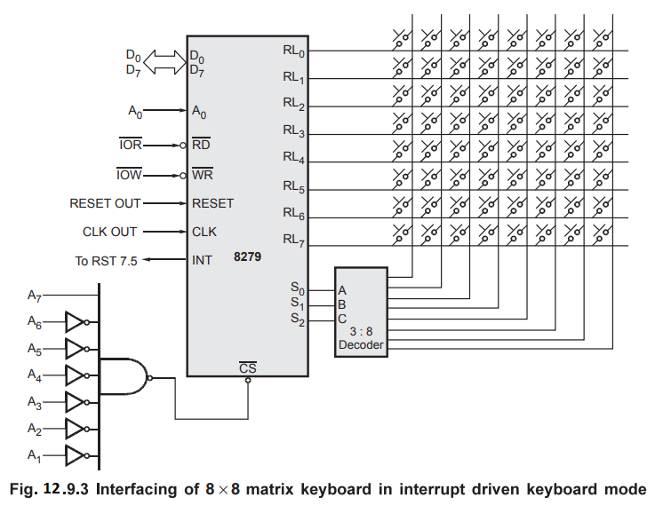
Hardware
: Fig. 12.9.2 shows the interfacing of 8 × 8 matrix keyboard in interrupt
driven keyboard mode.
In
the interrupt driven mode interrupt line from 8279 is connected to the one of
the interrupt input of 8085 except INTR. Here, INT line from 8279 is connected
to the interrupt RST 7.5 of 8085. Other signal connections are same as in the
non interrupt mode.
Software
:
All the command words required to initialize 8279 are same as in the non
interrupt mode.
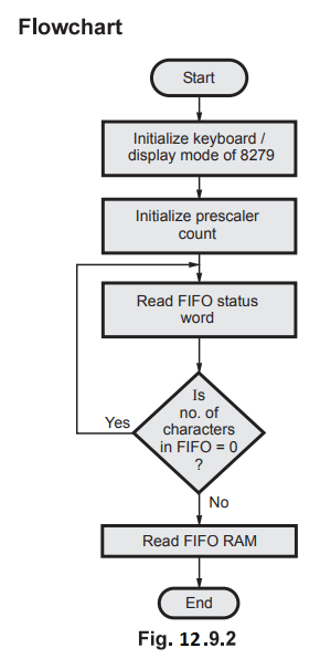
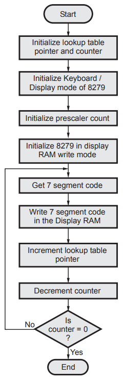
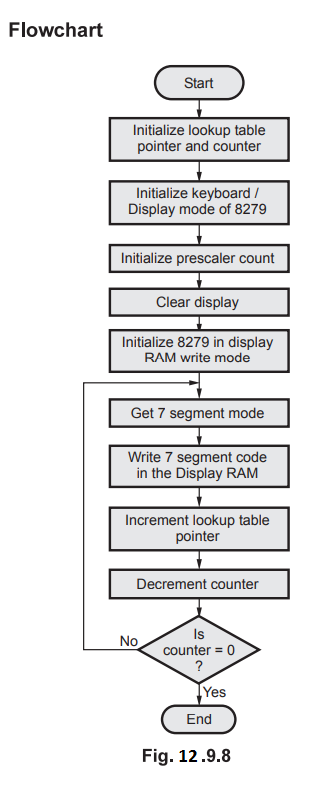
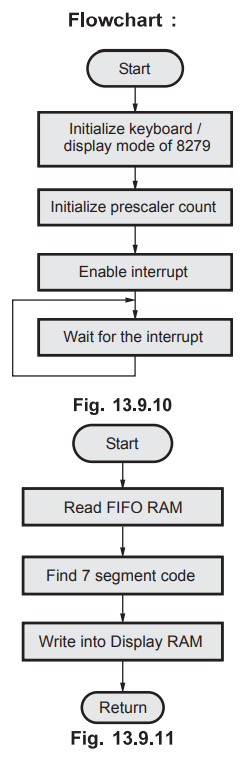
Flowchart
:
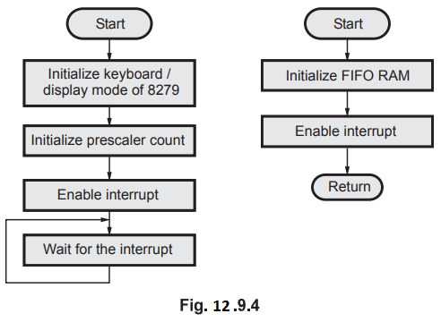
Main
Program :
MVI
A, 00H
OUT
81H ; Initialize keyboard/display in encoded
;
scan keyboard 2 key lockout mode
MVI
A, 34H
OUT
81H ; Initialize prescaler count
MVI
A, 0BH ; Load mask pattern to enable RST 7.5 and mask other interrupts
SIM
EI
; Enable interrupt
HERE
: JMP HERE ; Wait for the interrupt
Interrupt
Subroutine :
MVI
A, 40H ; Initialize 8279 in read
FIFO
OUT
81H ; RAM mode
IN
80H ; Read FIFO RAM (keycode)
EI
; Enable interrupt
RET
; Return to main program
In
the interrupt driven keyboard, when key is pressed, key code is loaded into
FIFO RAM and interrupt is generated. This interrupt signal is used to tell CPU
that there is a keycode in the FIFO RAM. CPU then initiates read command with
in the interrupt service routine to read keycode from the FIFO RAM.
Lab Experiment 12.9.2 : Hardware and
software to interface 8×4 matrix keyboard using 8279
Statement :
Interface an 8 x 4 matrix keyboard to 8085 through 8279.
Solution
:
Fig. 12.9.5 shows interfacing of an 8 x 4 matrix keyboard to 8085 through 8279.
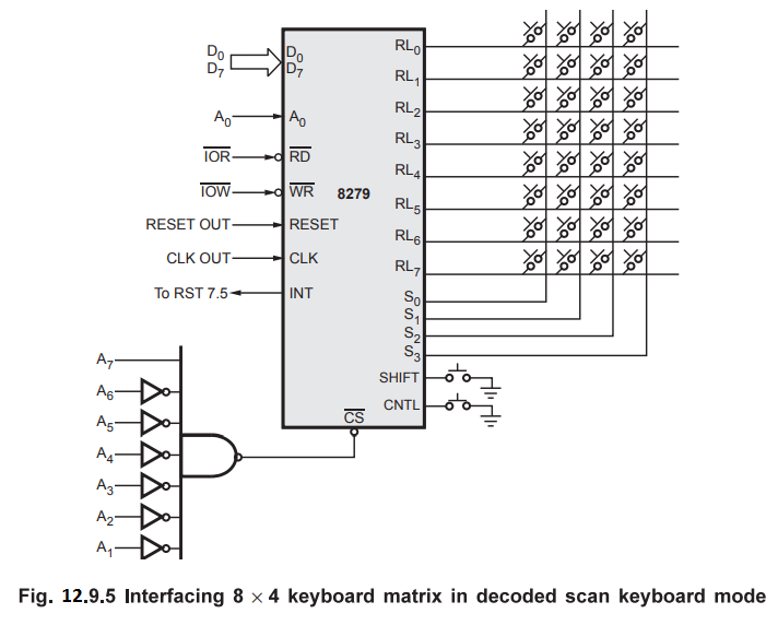
As
keyboard is having 8 rows and 4 columns, only 4 scan lines are required and we
can avoid external decoder to generate scan lines by selecting decoded scan
keyboard mode.
Main
Program :
MVI
A, 00H
OUT
81H ; Initialize keyboard/display in encoded
;
scan keyboard 2 key lockout mode
MVI
A, 34H
OUT
81H ; Initialize prescaler count
MVI
A, 0BH ; Load mask pattern to enable RST 7.5
;
and mask other interrupts
SIM
EI
; Enable Interrupt
HERE
: JMP HERE ; Wait for the interrupt
Interrupt
Subroutine :
MVI
A, 40H ; Initialize 8279 in read FIFO
OUT
81H ; RAM mode
IN
80H ; Read FIFO RAM (keycode)
EI
; Enable Interrupt
RET ; Return to main program
Lab Experiment 12.9.3 : Hardware and
software to interface eight 7-segment digits using 8279.
Statement :
Interface 8/7-segment digits (common cathode) to 8085 through 8279 and write an
8085 assembly language program to display 1 to 8 on the eight seven segment
digits. External clock frequency is 3 MHz.
Solution
: Fig. 12.9.6 shows the interfacing of eight 7-segment digits to 8085 through
8279.
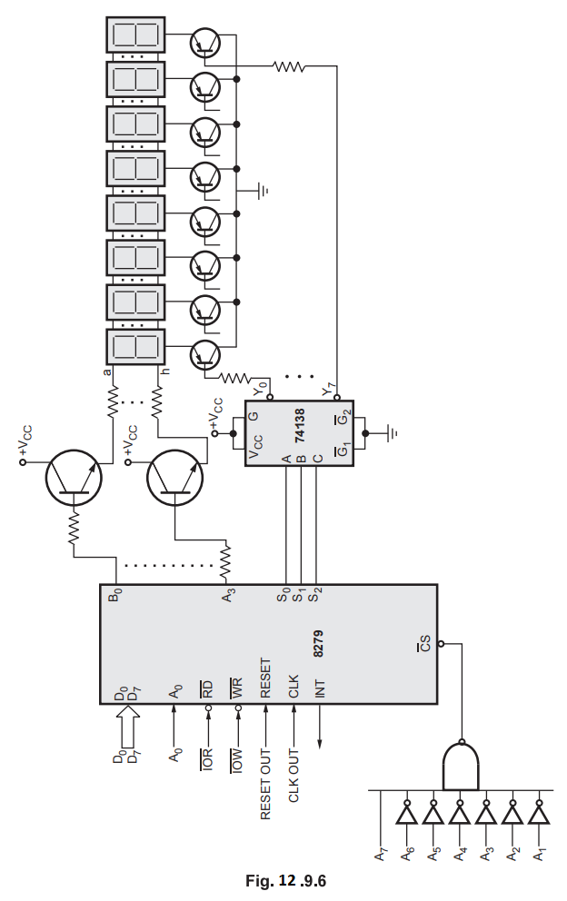
As
shown in the Fig. 12.9.6, eight display lines (B0-B3 and A0-A3)
are buffered with the help of transistor and used to drive display digits.
These buffered lines are connected in parallel to all display digits. S0,
S1 and S2 lines are decoded and decoded lines are used
for selection of one of the eight digits.
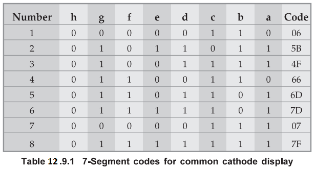
Software
:
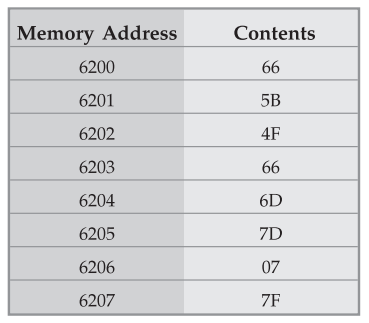
To display 1 to 8 numbers on the eight 7-segment digits we have to load
7-segment codes for 1 to 8 numbers in the corresponding display locations.
Step
1 :
Find keyboard/display command word. To interface 8 digit 7 segment display we
need 8/8-bit character display mode with left entry. For selection of 8 digits
we need encoded scan mode. Therefore, the keyboard/display command word is as
given below.
Step
2 :
Find program clock command word. External clock frequency is 3 MHz.
Prescaler
value = 3 MHz / 100 MHz = 30 = (11110)2
Therefore,
the program clock command word is as given below
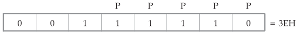
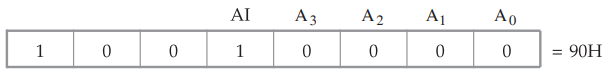
Step
3 : Find
write display RAM command word. We want to write first eight locations with
autoincrement mode by command word given below.
Program
:
LXI
H, 6200H ; Initialize lookup table
;
pointer
MVI
C, 80H ; Initialize counter
MVI
A, 00H ; Initialize keyboard/display
OUT
81H ; Mode
MVI
A, 3EH ; Initialize prescaler count
OUT
81H
MVI
A, 90H ; Initialize 8279 in write
;
Display
OUT
81H ; RAM mode
BACK
: MOV A,M ; Get the 7-segment code
OUT
80H ; Write 7-segment code in
;
display RAM
INXH
; Increment lookup table
;
pointer
DCR
C ; Decrement counter
JNZ
BACK ; if count = 0 stop otherwise
;
go to back
HLT ; Stop program execution
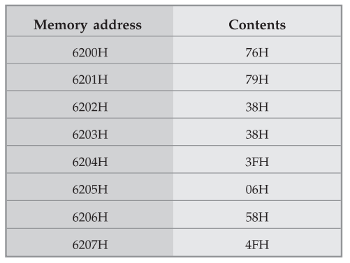
Lookup table:
Lab Experiment 12.9.4 : Write an
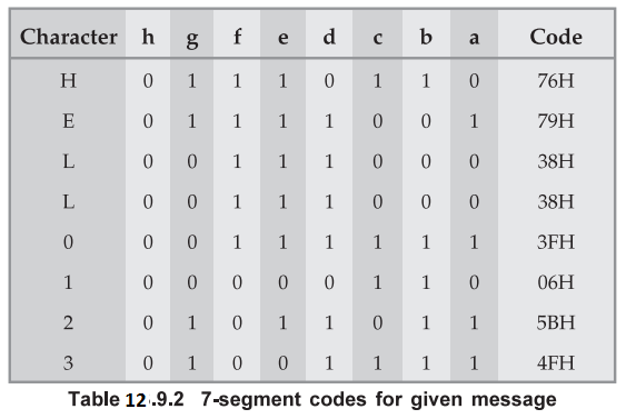
assembly language program to roll message 'HELL0123'.
Statement :
Using hardware same as in the example 3, write an assembly language program to
roll message 'HELLO123' from right to left.
Solution
:
To roll above message we have to load 7-segment codes for characters within the
message and it is necessary to configure 8279 in right entry mode.
Step
1 :
Find keyboard/display command word
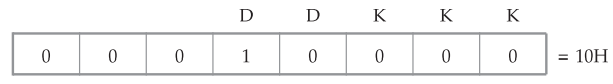
Note
DD = 10 = 8 8-bit character display right entry.
Program
clock command word and write display RAM command word are same as in the
previous example.
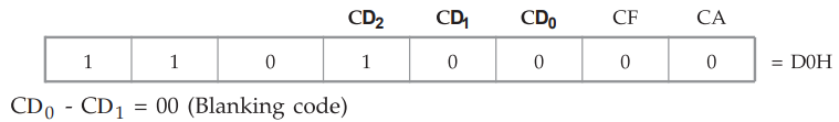
Clear
command word
Program
:
LXI
H, 6200H ; Initialize lookup table pointer
MVI
C,08H ; Initialize counter
MVI
A.10H ; Initialize keyboard/display
in right entry mode.
OUT
81H ; Mode
MVI
A,34H ; Initialize prescaler
count
OUT
81H
MVI
A, D0H ; Clear display
OUT
81H
MVI
A, 90H ; Initialize 8279 in write display
OUT
81H ; RAM mode
BACK
: MOV A,M ; Get the 7-segment code
OUT
80H ; Write 7 segment code in display RAM
INXH ; Increment lookup table pointer
DCR
C ; Decrement counter
JNZ
BACK ; If count-0 stop ; otherwise
;
goto BACK
HLT
; Stop program execution
Lookup
table :
Lab Experiment 12.9.5 : Interface 4X4
matrix keyboard and 4 digit 7-segment display using 8279
Statement :
Interface 4×4 matrix keyboard and 4 digit 7-segment display and write an
assembly language program to read keycode of the pressed key and display same
key on the 7 segment display.
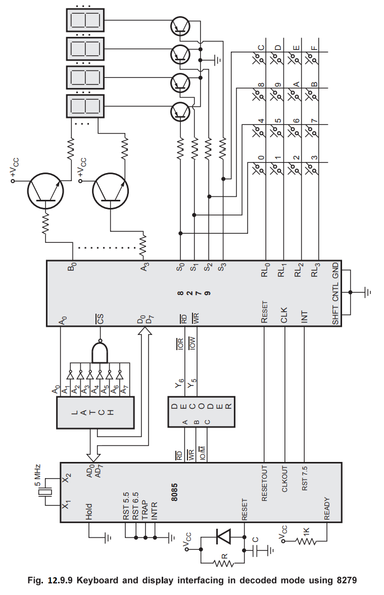
Solution
: Fig.
12.9.9 shows interfacing diagram. Here, only 4 scan lines are sufficient to
scan matrix keyboard and to select display digits. Hence decoded mode is used.
Software
:
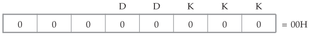
Step
1 :
Find keyboard / display command word.
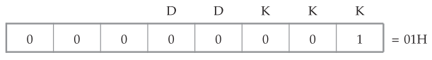
DD
= 00 8/8-bit character display left entry
KKK = 001-Decoded scan keyboard-2 key lockout
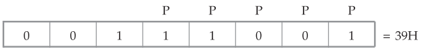
Step
2 :
Find program clock command word.
External
clock frequency is 2.5 MHz
ஃ Prescaler value = 2.5 MHz / 100kHz
= 25 (11001)2
Therefore,
the program clock command word is as given below
Step
3 :
Find Read FIFO RAM command word. We want to read first entry from the FIFO RAM.
Therefore command word is as given below.
Step
4 :
Find Write FIFO RAM command word.
We
have to display at a time only single key number. Here mode is not required.
Interrupt
Service Routine :
Program
:
MVI
A, 00H ; Initialize keyboard / display in
OUT
81H ; encoded scan keyboard 2-key
;
lockout mode.
MVI
A, 39H ; Initialize prescaler count
OUT
81H
MVI
A, 0BH ; load mask pattern to enable
RST
7.5
SIM
; and mask other interrupts
EI
; Enable interrupt
HERE
: JMP HERE ; Wait for the interrupt
Interrupt
Service routine :
MVI
A, 40H ; Initialize 8279 in read FIFO RAM mode
OUT
81H
IN
80H ; Get dat from RAM
MVI
H, 62H ; Initialize memory pointer to point
MOV
L,A ; 7-Segment code
MVI
A, 80H ; Initialize 8279 in write display RAM
;
mode
OUT
81H
MOV
A,M ; Get the 7-segment code
OUT
80H ; Write 7-segment code in display RAM
EI
; Enable interrupt
RET
; Return to main program
Review Questions
1. Write a program
using RST 5.5 interrupt to get an input from keyboard and display it on the display
system.
AU : May-05, Marks 6
2. Using peripheral
mapped I/O, design a seven segment LED output port with device address of F2h
using necessary control ICs. Draw the schematic and write 8085 ALP for
displaying digit 8.
AU : May-07, Marks 8
3. How is keyboard
interfaced with microprocessor ?
AU : Dec.-17 Marks 2
Microprocessors and Microcontrollers: Unit IV: (e) Keyboard and Display Controller - 8279 : Tag: : Keyboard and Display Controller - 8279 - Applications