Electric Circuit Analysis: Unit IV: Three phase circuits
Balanced delta connected load
Three phase circuits
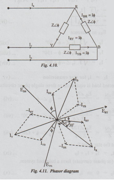
Fig.4.10 shows a balanced delta - connected load of impedance Z in each phase.
BALANCED DELTA CONNECTED LOAD
Fig.4.10
shows a balanced delta - connected load of impedance Z in each phase.
Z
= | Z| ∠ϕ
The
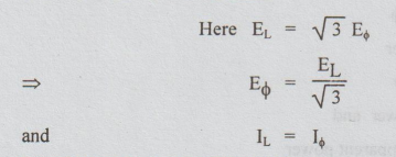
phasor diagram is also shown in fig.4.10.
Assume
the phase sequence to be RYB. Taking ERY as reference

Expression
for total power in a 3 phase balanced circuit
Let
E ϕ
= Voltage per phase
I
ϕ
= Current per phase
cos
ϕ Power factor of the balanced load
Total
average power W = 3 E ϕ Iϕ cos ϕ … (i)
Usually,
this expression is expressed in terms of line voltage and line current as
below:
Case
(1):
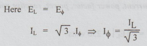
Star connected load:
Substituting
these values in equation (i)

Case
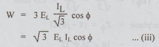
(2): Delta connected load:
Putting
these values in equation (i), we get
EL
and IL are in volts and amperes respectively.
Then
the power W is in watts. Dividing both sides of the equation (iii) by 1000, we
get:
W
/ 1000 = √3EL IL /
1000 cos ϕ
W/1000
is actual power or average power or a real power or true power. (denoted by P)
in KW.
√3EL
IL / 1000 is apparent power (denoted by S) and measured in KV
amperes (KVA).
KW
= KVA cos ϕ ... (iv)
From
equation (iv), we can draw the power triangle which is shown below:
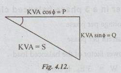
It
is right-angled triangle from which we get the relation S = P + jQ
⇒ S = √ P2 +
Q2 …. (v)
Here
P = KVA cos ϕ
=
active power
Q
= KVA sin ϕ
=
reactive power and
S
= KVA = apparent power
Electric Circuit Analysis: Unit IV: Three phase circuits : Tag: : Three phase circuits - Balanced delta connected load
Related Topics
Related Subjects

Electric Circuit Analysis
EE3251 2nd Semester 2021 Regulation | 2nd Semester EEE Dept 2021 Regulation