Basic Civil & Mechanical Engineering: UNIT IV: b. Boilers
Boiler Mountings
Description, Working Principle, Layout Diagram
For the safe operation, satisfactory functioning, efficient working and easy maintenance of the boilers, Boiler Mountings are provided as per the Indian Boiler Act.
BOILER MOUNTINGS
For
the safe operation, satisfactory functioning, efficient working and easy
maintenance of the boilers, Boiler Mountings are provided as per the Indian
Boiler Act. These include:
1.
Water Gauge (Water Level Indicator)
2.
Pressure Gauge
3.
Safety Valves
(b)
Spring Loaded Safety Valve
(d)
High Steam Low Water Safety Valve
4
. Fusible Plug
5.
Feed Check Valve
6.
Stop Valve
7.
Blow-off Cock
1. WATER GAUGE (WATER LEVEL INDICATOR)
It
indicates the water level inside the boiler and is hence called Water Level
Indicator. Two water gauges are fitted in a boiler as per Indian Boiler Act.
Description
(Fig. 5)
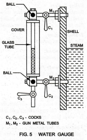
It
consists of a glass tube, two gun metal tubes and three cocks. The steam cock C1
is provided on the gun metal tube M1 which connects the glass tube
with the steam space in the boiler. The water cock C2 is provided on
the gun metal tube M2 which connects the glass tube with the water
space. The gun metal tubes M1 and M2 are bolted to the
boiler shell.
The
drain cock C3 is used to drain the water from the glass tube at
intervals to ascertain whether the gauge is in proper order or not. The glass
tube is protected by means of a cover, made of specially toughened glass. The
cover will prevent any accident that may happen due to the breaking of the
glass tube.
Working
The
water gauge shows the level of water in the boiler drum. It warns the operator
if the water level goes below a fixed mark, so that corrective action may be taken
in time to avoid any accident.
.
For the observation of the water level in the boiler, the water and steam cocks
are opened and the drain cock is closed. The steam enters from the upper metal
tube Mi into the glass tube. Also, water enters from the lower metal tube M2
into the glass tube. Hence, water stands in the glass tube at the same level as
in the boiler.
The
junctions of the metal tubes and the glass tube are provided with two balls. In
case the glass tube is broken, the balls are pushed to the top and bottom ends
of the glass tube. Thus, the flow of both water and steam out of the boiler is
prevented.
2. PRESSURE GAUGE (BOURDON TYPE )
A
pressure gauge is used to indicate the steam pressure of the boiler. It is also
called Steam Gauge. It is usually mounted in the front top of the steam drum.
Description
(Fig. 6): Fig. 6 shows a commonly used pressure gauge known as
Bourdon type. It consists of an elastic metallic Bourdon spring tube S. of
elliptical cross section and bent in the form of circular arc. One end of the
tube is fixed at the block B. It is connected to the steam space of the boiler
by means of a cock C.
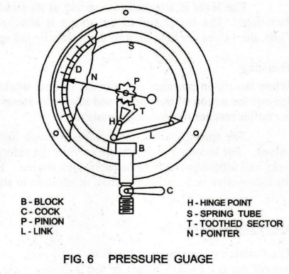
The
other end is connected to a toothed sector T through a link L hinged at the
point H. The sector is in mesh with a pinion P fixed on a spindle. An
indicating pointer N is attached to the spindle to read the pressure on a dial
gauge D.
Working:
When steam enters the elliptical tube, the tube section tries to become
circular. This causes the other end of the tube to move outward. The movement
of the closed end of the tube is transmitted and magnified by link and toothed
sector. Magnitude of the movement of the sector is indicated by the pointer on
the dial.
Note:
Spring tube is surrounded by atmospheric air. So, the pressure in the interior
of the tube is above that of the atmosphere, i.e., Absolute pressure = Gauge
Pressure + Atmospheric Pressure.
3. SAFETY VALVES
Safety
Valves are used to maintain a constant safe pressure inside the boiler. When
the pressure inside the boiler increases, the excess steam will escape to the
atmosphere through the valve automatically. A boiler is provided with two
safety valves as per the Indian Boiler Act.
There
are four different types of safety valves, viz., (a) Dead Weight Safety Valve,
(b) Lever Safety Valve, (c) Spring Loaded Safety Valve and (d) High Steam Low
Water Safety Valve. Spring loaded safety valve is the most commonly used.
a.
Spring Loaded Safety Valve (Ramsbottom
Safety Valve)
Description
(Fig. 7)
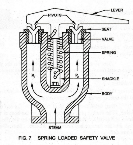
Ramsbottom
safety valve is loaded with a spring instead of weights. Hence, it is called
Spring Loaded Safety Valve. It consists of a Cast Iron Body having Two Branch
Pipes P1 and P2.
Two
Separate Valves are placed over the valve seatings, which are fixed to the top
of the branch pipes. A Lever is placed over the valves by means of two conical
pivots.
The
lever is attached to a spring at its middle. The spring pulls the lever in
downward direction. The lower end of the spring is attached to the valve body
by means of a shackle. Thus, the valves are held tight to their seats by the
spring force.
Working
When
the steam pressure exceeds the normal working pressure in the boiler, the
valves rise up against the action of the spring and allow the steam to escape
from the boiler till the pressure in the boiler reaches its working pressure.
The
spring loaded safety valve is much lighter and compact compared with other safety
valves. For locomotive or marine service, the safety valve should be such that
it is unaffected by jerks and vibration likely to occur in such device. Hence,
spring loaded safety valve is preferred for locomotive and marine services, in
addition to stationary boilers.
4. FUSIBLE PLUG
The
function of the fusible plug is to put-off the fire in the furnace of the
boiler when the water level falls below the normal level. Thus, it avoids the
explosion which may take place due to overheating of the tubes and the shell.
Description
[Fig. 8]
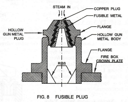
It
consists of a hollow gun metal body screwed into the fire box crown plate. A
hollow gun metal plug is screwed into the gun metal body by tightening the
hexagonal flange in it.
There
is another copper plug locked with the gun metal plug by pouring a low melting
point metal (lead) into the groove provided for the same.
Working
During
the normal operation, the fusible plug is submerged in water which keeps the
temperature of the fusible metal below its melting point.
A
But, when the water level falls below the top of the fusible plug, it is
uncovered by the water. The fusible plug therefore melts by the heat of the
furnace. Thus, the copper plug drops down and is held within the gun metal body
by the ribs. The opening so made allows the steam rush into the furnace and
extinguish the fire. Thus, damage to the fire box which could burn up, is
avoided.
Basic Civil & Mechanical Engineering: UNIT IV: b. Boilers : Tag: : Description, Working Principle, Layout Diagram - Boiler Mountings
Related Topics
Related Subjects

Basic Civil and Mechanical Engineering
BE3255 2nd Semester 2021 Regulation | 2nd Semester EEE Dept 2021 Regulation