Electrical Machines II: UNIT I: c. Synchronization and Parallel Operation of Alternators
Capability Curves
Synchronous Generator or Alternator
The heating is caused by losses so ultimately rating of machine depends on losses.
Capability Curves
Before
studying what are capability curves of synchronous generator, let us first
discuss about rating of generators and its compounding curves. The heating is a
key factor in deciding the rating of alternators, transformers etc. The heating
is caused by losses so ultimately rating of machine depends on losses. These
losses are independent of load p.f. as I2R losses depend on current while core
losses are dependent on voltage. Thus the rating of a.c. equipments is decided
by the volt-amperes of the load it can supply and not on load power only. In
case of turbines and boilers in hydroelectric and thermal stations, their
sizes, water and fuel requirements depend on output power.
The
rating of synchronous generators is specified interms of maximum apparent power
in kVA and MVA load at a specified power factor (normally 80, 85 or 90 percent
lagging) and voltage for which they are designed to operate under steady state
conditions. This load is carried by the alternators continuously without
overheating. With the help of automatic voltage regulators the terminal voltage
of the alternator is kept constant (normally within ± 5 % of rated voltage).
The
power factor is also important factor that must be specified. This is because
the alternator that is designed to operate at 0.95 p.f. lagging at rated load
will require more field current when operated at 0.85 p.f. lagging at rated
load. More field current results in overheating of the field system which is
undesirable. For this compounding curves of the alternators can be drawn.
If
synchronous generator is supplying power at constant frequency to a load whose
power factor is constant then curve showing variation of field current versus
armature current when constant power factor load is varied is called
compounding curve for alternator. It is shown in Fig. 3.19.1.
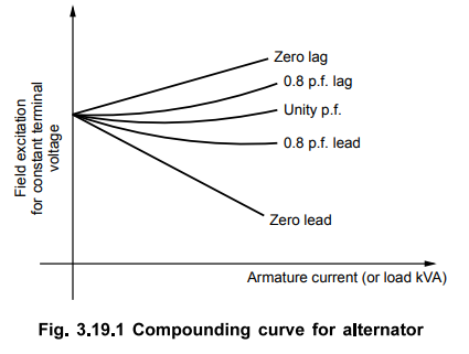
To
maintain the terminal voltage constant the lagging power factors require more
field excitation than that required for leading power factors. Hence there is
limitation on output given by exciter and current flowing in field coils
because of lagging power factors.
The
ability of prime mover decides the active power output of the alternator which
is limited to a value within the apparent power rating. The capability curve
for synchronous generator specifies the bounds within which it can operate
safely. The loading on generator should not exceed the generator rating as it
may lead to heating of stator. The turbine rating is the limiting factor for MW
loading. The operation of generator should be away from steady state stability
limit (8 = 90°). The field current should not exceed its limiting value as it
may cause rotor heating. All these considerations provides performance curves
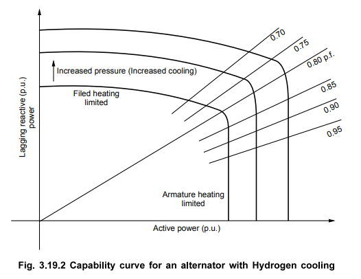
which are important in practical applications. A set of capability curves for
an alternator is shown in Fig. 3.19.2. The effect of increased Hydrogen
pressure is shown which increases the cooling.
When
the active power and voltage are fixed the allowable reactive power loading is
limited by either armature or field winding heating. From the capability curve
shown in Fig. 3.19.2, the maximum reactive power loadings can be obtained for
different power loadings with the operation at rated voltage. From unity p.f.
to rated p.f. (0.8 as shown in Fig. 3.19.2), the limiting factor is armature
heating while for lower power factors field heating is limiting factor.
This
fact can be derived as follows :
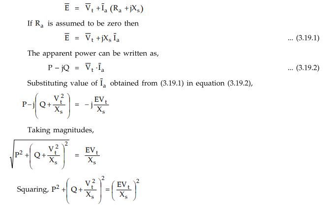
If
the alternator is operating at constant terminal voltage and armature current
which the limiting value corresponding to heating then the operation of
alternator is at constant value of apparent power as the apparent power is
product of terminal voltage and current, both of which are constant.
If
P is per unit active power and Q is per unit reactive power then per unit
apparent power is given by,
Apparent
power = √P2 + Q2
= Vt • Ia
Thus
we have,
√P2
+ Q2 = Vt • Ia
Squaring,
√P2 + Q2 = (Vt • Ia )2
The
above equation represents a circle with center at origin and radius equal to Vt
• Ia
Similarly,
considering the alternator to be operating at constant terminal voltage and
field current (hence E) is limited to a maximum value obtained by heating
limits.
This
equation also represents a circle with centre at (D, Vt2
/ Xs ). These two circles are represented in the Fig. 3.19.3.
The field heating and armature heating limitations on machine operation can be
seen from this Fig. 3.19.3
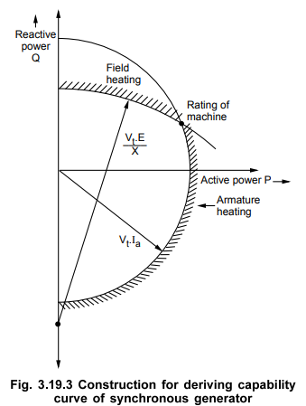
The
rating of machine which consists of apparent power and power factor is
specified as the point of intersection of these circles as shown in the
Fig.3.19.3. So that the machine operates safely.
Review Questions
1. Write short note on
capability curves of synchronous generator.
2. Elaborate the
discussion on capability curve with its boundaries of synchronous machine. AU : Dec.-06, 10,
Marks 8
Electrical Machines II: UNIT I: c. Synchronization and Parallel Operation of Alternators : Tag: Engineering Electrical Machines - II : Synchronous Generator or Alternator - Capability Curves
Related Topics
Related Subjects

Electrical Machines II
EE3405 Machine 2 EM 2 4th Semester EEE Dept | 2021 Regulation | 4th Semester EEE Dept 2021 Regulation