Transmission and Distribution: Unit I: Transmission Line Parameters
Capacitance of a Three Phase Line with Equilateral Spacing
Diagram - Examples
Consider the three conductors a, b and c of 3 phase overhead transmission line having the charges qa, qb and qc respectively
Capacitance of a Three
Phase Line with Equilateral Spacing
Consider the three conductors a, b and c
of 3 phase overhead transmission line having the charges qa, qb
and qc respectively as shown in Fig. 1.29.1. Let the conductors be
separated from each other by a distance of d from each other and placed on the
vertices of equilateral triangle.
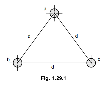
The radius of each conductor is say r.
The voltage Vab of the three phase line due to only charges on
conductors a and b is given by,
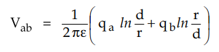
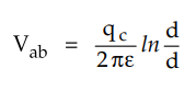
Voltage Vab due to only
charge qc is zero as uniform charge distribution over the surface of the
conductor is equivalent to a concentrated charge at the centre of conductor.
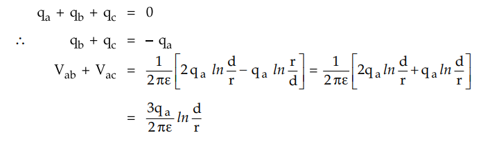
Considering all the three charges in
writing the voltage equation we have,
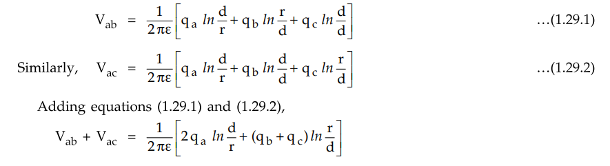
The voltages are sinusoidal and
expressed as the phasors. In absence of other charges in the vicinity the sum
of the charges is zero i.e.
The Fig. 1.29.2 shows phasor diagram of
balanced voltages of three phase line.
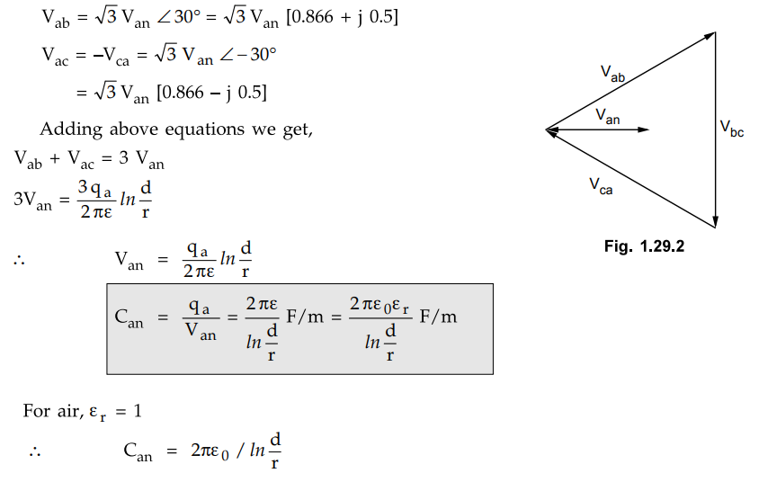
It can be seen that capacitance to
neutral for single phase and equilaterally spaced three phase lines is same.
The current associated with capacitance
of a transmission line is termed as charging current. In case of single phase
circuits, the charging current is the product of line to line voltage and line
to line susceptance.
IC = j ω Cab Vab
In case of three phase circuits, the
charging current is found by product of voltage to neutral and capacitive susceptance
to neutral. The charging current obtained is for one phase. The current in any
phase is given by,
Ic = j ω CnVan
The charging current is not same
everywhere as the rms voltage along line varies. For obtaining the charging
current the value of voltage used is that for which the line is designed which
may not be actual voltage at either generating station or a load.
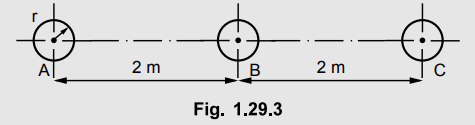
Example 1.29.1
A 3 phase, 50 Hz, 110 kV overhead line conductors are placed in a horizontal
plane as shown in the Fig. 1.29.3. The conductor diameter is 1.5 cm. If the
line length is 100 km. Calculate i) Capacitance/phase ii) Charging
current/phase assuming complete transposition of the line. Assume line
transposition.
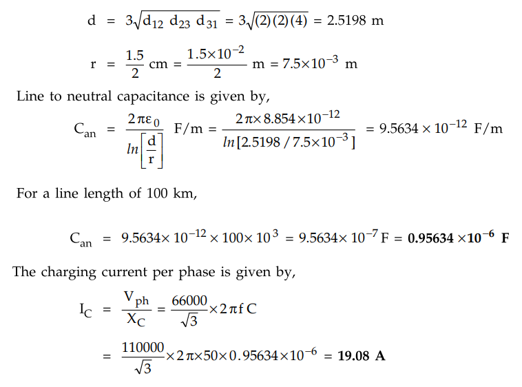
Solution :
Equivalent equilateral spacing is given by,
Example 1.29.2
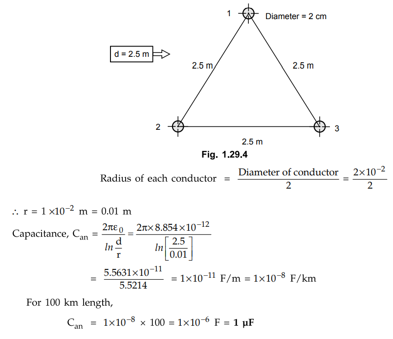
Calculate the capacitance of a 100 km long 3-phase, 50 Hz overhead
transmission line consisting of 3 conductors each of diameter 2 cm and spaced
2.5 m at the comers of an equilateral triangle.
Solution :
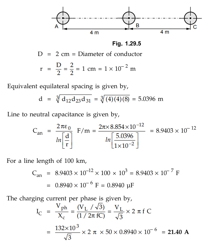
Example 1.29.3
A 3-phase, 50 Hz, 132 kV overhead line has conductors placed in a horizontal
plane 4 m apart. Conductor diameter is 2 cm. If the line length is 100 km,
calculate the charging current per phase assuming complete transposition.
AU : Dec.-08, May-18, Marks 8
Solution :
Review Questions
1. Derive the expression for the capacitance to neutral of
a three phase line with equilateral spacing.
May-06, 07, Dec.-07, Marks 8
2. A three-phase, 50 Hz, 132 kV overhead line has conductor
placed in horizontal plane 4 m apart. Conductor diameter is 2 cm. If the line
length is 100 km. Calculate :
i) Capacitance of each conductor to neutral ii) Charging
current per phase.
Assuming complete transposition.
[Ans.: 0.8940 x10“6 F, 21.40 A]
3. A 200 km, 3 phase transmission line has its conductors
placed at comers of equilateral triangle of 2.5 m side. The radius of each conductor
is 1 cm calculate
i) Line to neutral capacitance of line
ii) Charging current per phase for voltage of 66 kV, 50 Hz.
[Ans.: 2.02 µF, 24.2 A]
4. Three conductors A, B and C of a 3 phase line are arranged
in a horizontal plane with DAB = 2 m and DBC = 2.5 m.
Find line to neutral capacitance per km if diameter of each conductor is 1.24
cm. The conductors are transposed at regular intervals
[Ans.: 0.0091 µF/km]
Transmission and Distribution: Unit I: Transmission Line Parameters : Tag: : Diagram - Examples - Capacitance of a Three Phase Line with Equilateral Spacing
Related Topics
Related Subjects

Transmission and Distribution
EE3401 TD 4th Semester EEE Dept | 2021 Regulation | 4th Semester EEE Dept 2021 Regulation