Digital Logic Circuits: Unit II: Combinational Circuits
Code Converters
K-map simplification design | Combinational Circuits
• There is a wide variety of binary codes used in digital systems. Some of these codes are Binary-Coded-Decimal (BCD), Excess-3, Gray and so on. Many times it is required to convert one code to another.
Code Converters
AU
: Dec.-03, 11, 14, 15, 16, June-09, Hay-10, 11, 15, 16
•
There is a wide variety of binary codes used in digital systems. Some of these
codes are Binary-Coded-Decimal (BCD), Excess-3, Gray and so on. Many times it
is required to convert one code to another.
•
Let us see the procedure to design code converters :
Step
1 :
Write the truth table showing the relationship between input code and output
code.
Step
2 :
For each output code bit determine the simplified Boolean expression using
K-map.
Step
3 :
Realize the code converter using logic gates.
Examples
for Understanding
Ex.
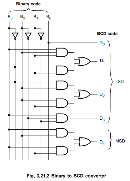
3.21.1 Design a 4-bit binary to BCD converter.
Step
1 : Form
the truth table relating binary and BCD code.
Input
code : Binary code : B3 B2 B1
B0 (B0 LSB)
Output
code : BCD (Decimal) code : D4 D3 D2
D1 D0 (D0 LSB)

Step
2 :
K-map simplification for each BCD output

Step
3 :
Realization of code converter
Ex.
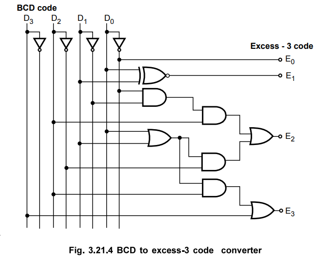
3.21.2 Design a logic circuit to convert the 8421 BCD to Excess-3 code.
Sol.
:
Step
1 :
Form the truth table relating BCD and Excess-3 code.
Excess-3
code is a modified form of a BCD number. The Excess-3 code can be derived from
the natural BCD code by adding 3 to each coded number. For example, decimal 12
can be represented in BCD as 0001 0010. Now adding 3 to each digit we get
Excess-3 code as 0100 0101 (12 in decimal). With this information the truth
table for BCD to Excess-3 code converter can be determined as shown in Table
3.21.2.

Input
code : BCD code : D3 D2 D1
D0 (D0 LSB)
Output
code : Excess-3 code : E3 E2 E1
E0 (E0 LSB)
Step
2 :
K-map simplification for each Excess-3 code output.

Step
3 :
Realization of code converter.
Ex.
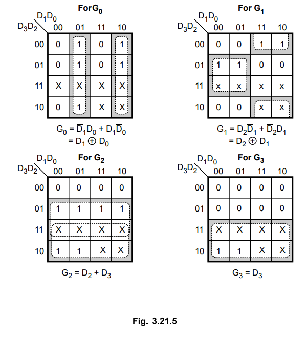
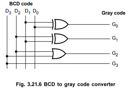
3.21.3 Design a logic circuit to convert BCD to gray code.
Solution
:
Step
1 :
Form the truth table relating BCD and gray code.
Input
code : BCD code : D3 D2 D1
D0 (D0 LSB)
Output
code : Gray code : G3 G2 G1 G0 (G0
LSB)
Table
3.21.3 shows truth table for BCD to gray code converter.

Step
2 :
K-map simplification
Step
3 :
Realization of code converter.
Ex.
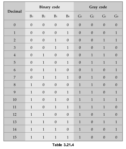
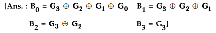
3.21.4 Design and implement a 8421 to Gray code converter. Realize the
converter using only NAND gates.
AU
: June-09, Marks 16, Dec.-14, 16, Marks 8
Sol.
:
Step
1 :
Form the Truth table relating 8421 binary code and BCD code
Input
code : Binary code : B3 B2 B1 B0
Output
code : Gray code : G3 G2 G1
G0
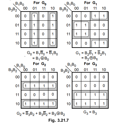
Step
2 :
K-map simplification for each gray code output
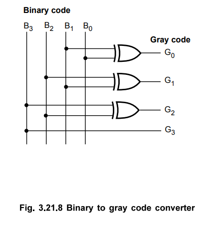
Step
3 :
Realization of code converter using XOR-gates
Step
4 : Realization
of code converter using NAND gates
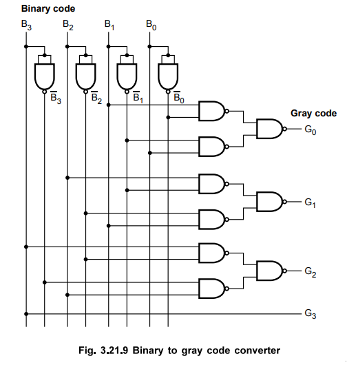
For this converter we have derived the Boolean
expressions for each gray code output in the Sum Of Product (SOP) form. We can
implement SOP expression using AND-OR logic or NAND-NAND logic. Let us see the
implementation of code converter using NAND-NAND logic.
Examples
for Practice
Ex.
3.21.5 Design a logic circuit to convert excess-3 code to BCD code.

Ex.
3.21.6 Design a logic circuit to convert gray code to binary code.
Review Question
1. Write brief note on binary to gray code converter.
AU : Dec.-11, Marks 4
Digital Logic Circuits: Unit II: Combinational Circuits : Tag: : K-map simplification design | Combinational Circuits - Code Converters
Related Topics
Related Subjects

Digital Logic Circuits
EE3302 3rd Semester EEE Dept | 2021 Regulation | 3rd Semester EEE Dept 2021 Regulation