Transmission and Distribution: Unit V: (a) Distribution Systems
Comparison of Conductor Material in Overhead System
Distribution Systems
Questions : 1. Calculate the volume of the conductor material required for 1-ϕ, 2 wire a.c. system with one conductor earthed for overhead transmission system. 2. Prove that the volume cf copper material required by three phase three wire system is 0.5 / cos2ϕ times the volume of copper required by two wire d.c. system, irrespective of whether system is star or delta connected, in overhead type of transmission. 3. Compare the various overhead a.c. and d.c. systems based on the volume of copper required. State the assumptions used. 4. Find the ratio of volume of copper required to transmit a given power over a given distance by overhead system using : i) D.C. 2 wire and 3 wire system, ii) 3ϕ, 3 wire AC system.
Comparison of Conductor
Material in Overhead System
AU : May-07, 13, Dec.-08
The selection of a particular type of
a.c. or d.c. system for the transmission and distribution is based on
comparison of amount of material i.e. copper necessary for the various systems.
As mentioned earlier, the maximum stress in the overhead system exists between
the conductor and earth. Hence comparison of material required is done assuming
the maximum voltage between any conductor and earth being the same. The
assumptions made for the comparison are :
1. The power (P) transmitted by all the
systems is same.
2. The distance (l) over which
the power is transmitted is same.
3. The power losses (W) in all the
systems are same.
4. The maximum voltage (Vm)
exists between any conductor and the earth, in all the systems.
Based on these assumptions, let us compare
the various types of systems for the volume of copper required.
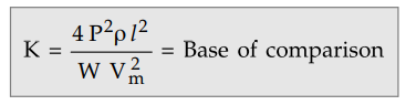
1. Two Wire D.C. System with One Line Earthed
The system is represented in the Fig.
7.16.1.
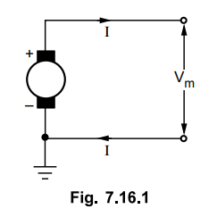
The maximum voltage between the
conductors is Vm, as one terminal is earthed.
The volume of copper required for other
systems is compared by taking volume of copper required for this system as
base. Let it be constant K and volume of copper required for other systems can
be expressed interms of K.
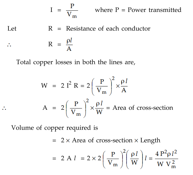
2. Two Wire D.C. System with Midpoint Earthed
The system is represented in the Fig.
7.16.2.
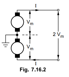
As power transmitted is same as P, the
current in each conductor is,
I = P / 2V m
The total copper loss in both the lines
is,
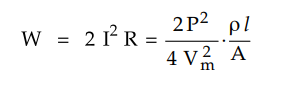
where A = Area of cross-section of each
line
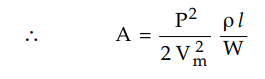
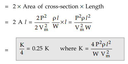
The total volume of copper required is,
Key Point
Thus the volume of copper required in this system is one fourth the volume
of copper required for two wire d.c. system with one line earthed.
3. Three Wire D.C. System
The system is represented as shown in
the Fig. 7.16.3.
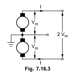
When the load is balanced, current
through the third neutral wire is zero.
I = P / 2Vm
Let A = cross-section of outer
conductors
The total copper loss is,
Let area of cross-section of the middle
neutral wire is half of the area of cross-section of the outer conductor.
Hence the total volume of copper
= Volume of copper for outer wires + Volume
of copper for neutral wire
Key Point
Thus the volume of copper required in this system is 0.3125 times the volume
of copper required for two wire d.c. system with one line earthed.
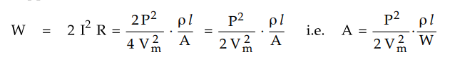
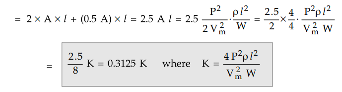
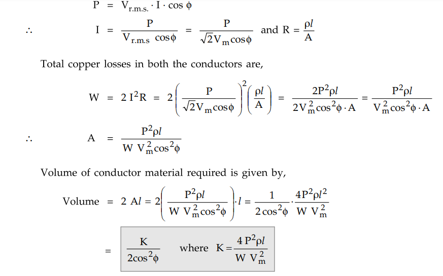
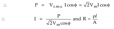
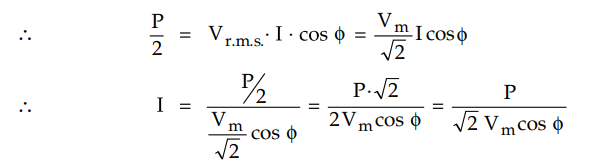
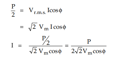
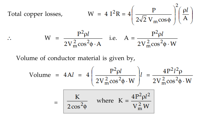
4. Two Wire Single Phase A.C. System with One Conductor Earthed
The system is represented in the Fig. 7.16.4.
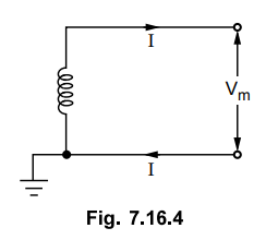
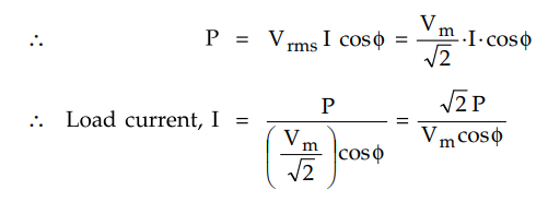
The maximum voltage between the conductors is Vm as one
terminal is earthed and the r.m.s. value of voltage is Vm / √2. Let the
power factor (p.f.) of the load be cos ϕ. Let the total power transmitted be P
watts.
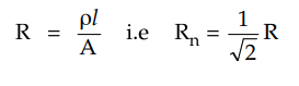
Let R be resistance of each conductor,
then R = ρl / A
Here A is area of cross-section of
conductor.
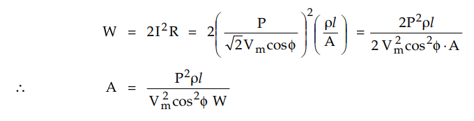
Total copper losses in both the
conductors are,
Key Point
Thus the volume of copper required in this system is1/cos2ϕ times
the volume of copper required for two wire d.c. system with one conductor
earthed.
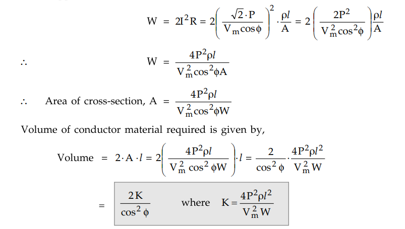
5. Two Wire Single Phase
A.C. System with Midpoint Earthed
The system is represented in the Fig. 7.16.5.
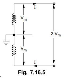
The voltage of the two wires with respect to earth is Vm. The voltage
between the two wires is 2 Vm and its r.m.s. value is 2Vm / √2 = √2
Vm. Let the p.f. of load be cos ϕ.
Let the power transmitted be P watts.
Thus the volume of copper required in
this system is 1 / cos2ϕ times the volume of copper required for two
wire d.c. system with one conductor earthed.
6. Three Wire Single Phase A.C. System
The system is represented in the Fig.
7.16.6. This system is similar to 3 wire d.c. system in principle.
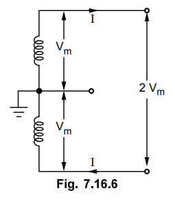
It consists of two outer wires and one
neutral wire taken from the midpoint of the phase winding.
If the load is assumed to be balanced
then the current in neutral will be zero. Let us consider this case.
Voltage between conductors = 2 Vm
R.M.S. value of voltage = 2 Vm
/ √2 = √2 Vm
Let the p.f. of load be cos ϕ and total
power transmitted be P watts.
Total copper losses in both the
conductors are,
Let the area of cross-section of the
middle neutral wire is half of the area of cross section of the outer
conductor.
Hence total volume of copper required is
given by,
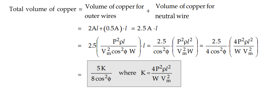
Key Point
Thus the volume of copper required in this system is 5/8cos2 ϕ of
times the volume of copper required for two wire d.c. system with one conductor
earthed.
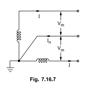
7. Three Wire Two Phase A.C. System
The system is represented as shown in
Fig. 7.16.7. The voltages of the two windings are in quadrature with each
other. From the junction of two phase windings, the neutral wire is taken. The
total power transmitted gets divided equally between the two windings and each
transmits one half of total power.
Let Vm be maximum voltage of
any one winding with respect to neutral while its r.m.s. value is Vm
/ √2.
Let the p.f. of load be cos 4 and power
transmitted by each outgoing conductor is P/2 where P is total power
transmitted.
The current in neutral wire is the
phasor sum of currents in outer wires. The currents are 90° apart (or in
quadrature) from each other. The magnitude of the current in neutral wire is
given as,
In = √I2 + I2
= √2.I
As the current in neutral wire is √2
times more than current in other conductors, the cross-section of neutral conductor
must be increased by √2 to have same current density.
Resistance of neutral wire,
Rn = ρl / An
But as its cross-section is increased,
its resistance is given as,

Here A is area of outer conductors and
its resistance is,
Total copper losses are given by,
W = Copper losses in outer conductors +
Copper losses in neutral conductor
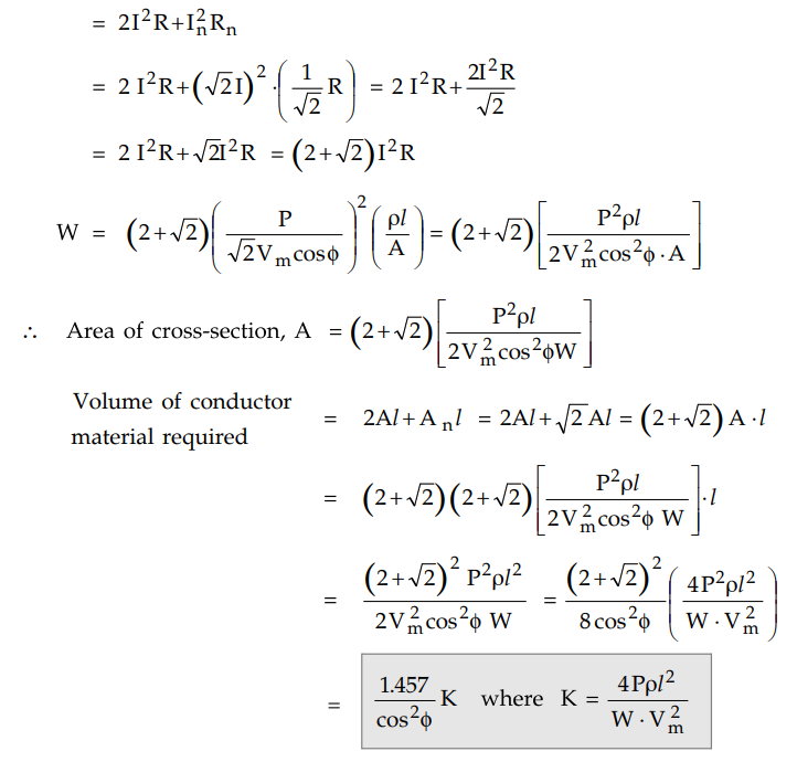
Key Point
Thus the volume of copper required in this system is 1.457/cos2 ϕ
times the volume of copper required for two wire d.c. system with one conductor
earthed.
8. Four Wire Two Phase A.C. System
The system is represented in the Fig.
7.16.8. The midpoints of the two windings are joined together. From the ends of
two phase windings, four wires are taken.
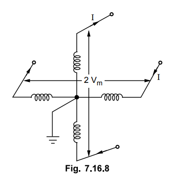
This system is equivalent to two
independent single phase systems with each system transmitting half of total
power.
Let Vm be maximum voltage of
any one winding with respect to earth and voltage between conductors is 2Vm
. The r.m.s. value of voltage is 2Vm / √ 2 = √2Vm.
Let p.f. of load be cos 0 and power
supplied by each outgoing conductor is P/2. We have,
Let R be resistance of each conductor
such that R = ρl / A where A is area of cross-section of conductor.
9. Three Phase Three Wire
A.C. System
This is most commonly used system for
the transmission. The three phase three wire star connected system with neutral
earthed is shown in the Fig. 7.16.9.
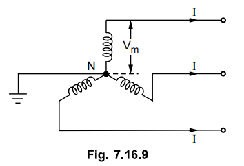
The maximum voltage between each line
conductor and the neutral is Vm as shown in the Fig. 7.16.9.
The r.m.s. value of the voltage per
phase is given by,
Vph = Vm / √2
The total power transmitted is P watts
hence per phase power transmission is,
Pph = P/3
Let cos ϕ be the load power factor
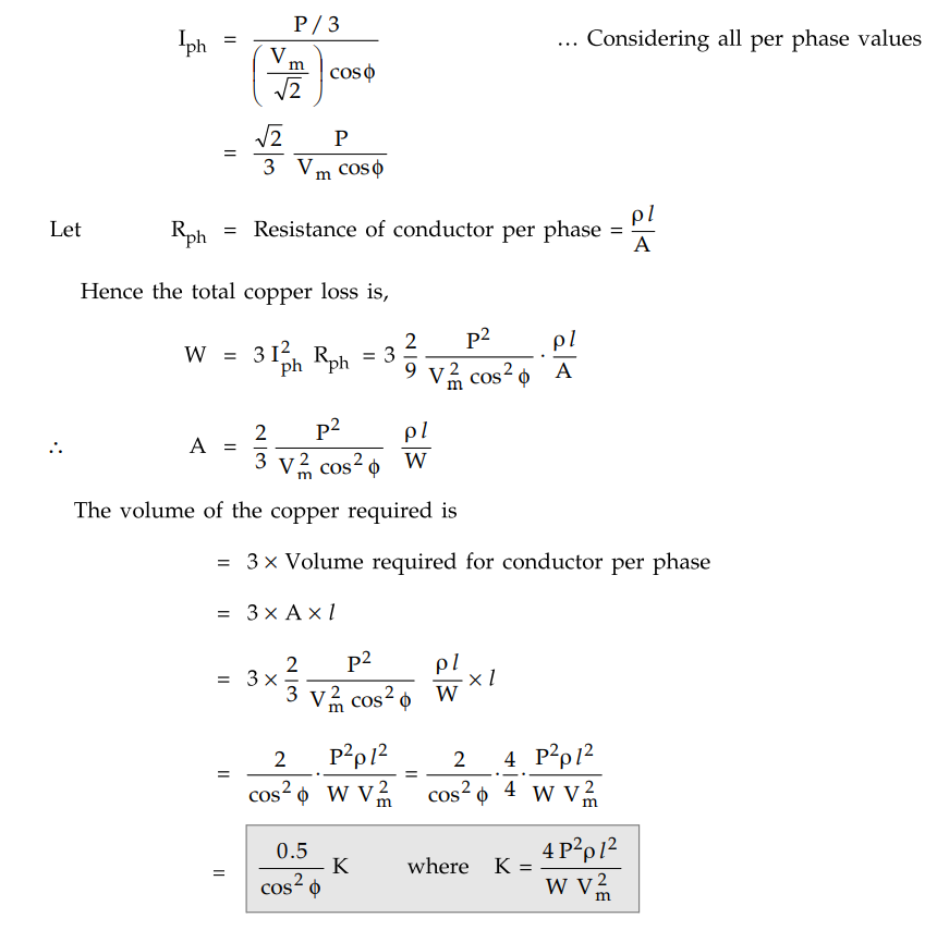
Key Point
Thus the volume of copper required, depends on power factor of the load and
it is 0.5/cos2ϕ times the volume of copper required bp two wire d.c.
system with one line earthed. This system may be delta connected but
irrespective of the method of connection star or delta, the result derived
remains same.
10. Three Phase Four Wire A.C. System
This system is popularly used for
secondary distribution. The neutral is also made available for the connection
of the load. The system is shown in the Fig. 7.16.10.
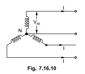
Assuming the load balanced, there is no
current flowing through the neutral.
The cross-section area of neutral is
half the cross-section of each conductor i.e. 0.5 A where A is cross-section of
each conductor.
The maximum voltage between any
conductor and voltage per phase is,
Vph = Vm / √2
The power transmitted per phase is,
Vph = P / 3
Hence all the calculations upto the
copper losses and expression of A remain same as derived for three phase three
wire system.
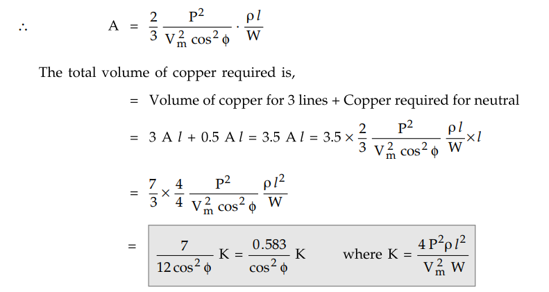
Key Point
Thus the volume of copper required is 0.583/cos2 ϕ times the volume
of copper required by two wire d.c. system with one line earthed.
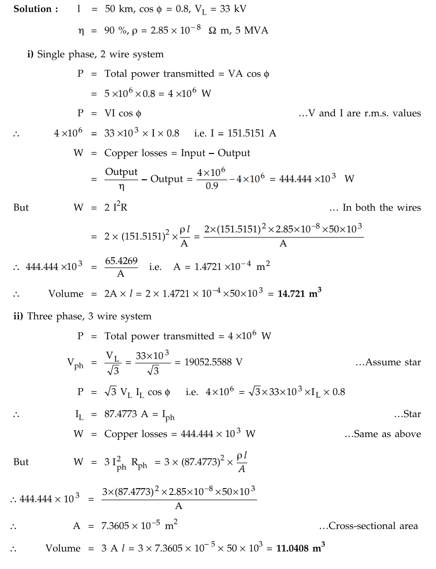
Example 7.16.1
A 50 km long transmission line supplies a load of 5 MV A at 0.8 p.f. lagging at
33 kV. The efficiency of transmission is 90 %. Calculate the volume of
aluminium conductor required for the line when i) single phase, 2-wire system
is used ii) 3-phase, 3 wire system is used. The specific resistance of
aluminimum is 2.85 × 10⁻⁸ Ω m.
Solution :
Review Questions
1. Calculate the volume of the conductor material required
for 1-ϕ, 2 wire a.c. system with one conductor earthed for overhead
transmission system.
2. Prove that the volume cf copper material required by
three phase three wire system is 0.5 / cos2ϕ times the volume of
copper required by two wire d.c. system, irrespective of whether system is star
or delta connected, in overhead type of transmission.
3. Compare the various overhead a.c. and d.c. systems based
on the volume of copper required. State the assumptions used.
4. Find the ratio of volume of copper required to transmit
a given power over a given distance by overhead system using :
i) D.C. 2 wire and 3 wire system, ii) 3ϕ, 3 wire AC system.
Transmission and Distribution: Unit V: (a) Distribution Systems : Tag: : Distribution Systems - Comparison of Conductor Material in Overhead System
Related Topics
Related Subjects

Transmission and Distribution
EE3401 TD 4th Semester EEE Dept | 2021 Regulation | 4th Semester EEE Dept 2021 Regulation