Transmission and Distribution: Unit V: (a) Distribution Systems
Concept of Power Factor Improvement
Power Triangle - Disadvantages - Causes of Low Power Factor
Questions : 1. Define power factor. State the causes of low power factor.
Concept of Power Factor
Improvement
The electrical energy is exclusively
generated and transmitted in the form of alternating current. And hence the
question of power factor immediately arises. The low power factor is
undesirable and for better engineering and economical conditions of supply
system, it is necessary to have power factor as close as unity. Let us see, why
it is so and how to improve it if it is very low.
1. Power Factor
In a.c. circuits the cosine of angle
between voltage and current is called as power factor.
We have seen that the angle between
voltage and current is called as power factor angle ϕ and it affects the active
power consumption. For inductive circuits ϕ is lagging while for capacitive
circuits it is leading in nature.

From the Fig. 7.19.1 it can be seen that
the current I in the circuit can be resolved into two components
i) I cos ϕ which is in phase with V
ii) I sin ϕ which is out of phase with V
by an angle of 90°
I cos ϕ is called active component or
wattful component while I sin ϕ is reactive or wattless component. Lesser the
value of this reactive component, smaller is the power factor angle or phase
angle ϕ and power factor cos ϕ will be high. Thus the circuit
with lesser reactive current component I sin ϕ will result in
higher power factor. Power factor always lies between zero and one never
exceeds unity.
The words lagging or leading are used
along with numerical value of power factor to indicate whether current is
lagging or leading with respect to voltage. The power factor can also be
expressed as a percentage. A power factor of 0.5 lagging can also be expressed
as 50 %.
So power consumption in a.c. circuits is
the product of voltage and the component of the current which is in phase with
the voltage. So if current is lagging with respect to voltage by angle ( then
active power consumption gets decided by the component Icos( , which is in
phase with the voltage, as shown in the Fig. 7.19.1
So for single phase circuits, the active
power is given by,
P = VI cos ϕ W
While for three phase circuits, the
active power is given by
P = √3 VL IL cos ϕ
w
In the three phase circuits, ϕ is the angle between phase voltage and the
phase current. We have seen the power triangle for three phase circuit which is
as shown in the Fig. 7.19.2.

So power factor can be defined as the
ratio of active power to apparent power. If the lagging reactive power
component is shown downwards then the leading reactive power component is shown
upwards. So lagging reactive power tries to lower the power factor while
compensating leading reactive power can increase the power factor. Hence
leading power factor loads is the key of power factor improvement.
2. Power Triangle
The power triangle is obtained by
multiplying each side of current triangle by voltage V. This is shown the Fig.
7.19.3.

The active power in watts or kW is represented
by OX which is VI cos ϕ . The reactive power in VAR or kVAR is represented by
XY which is VI sin ϕ . The apparent power in VA or kVA represented by or is
given by VI.
The apparent power (VI) has two
components viz. active and reactive which are perpendicular to each other.
By Pythagorous Theorem,

Lagging reactive power is drawn by the
circuit when current lags behind voltage while reactive power drawn is leading
when current leads voltage .
The power factor can also be given by,
Power factor, cos ϕ = R/ Z = Resistance / Impedance
The power triangle for capacitive circuit is as shown in the Fig. 7.19.4.

This triangle is opposite to that in
case of lagging load. Thus if capacitor is connected in parallel with the load
which has lagging power factor in order to improve overall power factor of the
circuit then the lagging reactive power of the load is partly neutralized.
The reactive power is never actually
consumed in the circuit. It is not doing any useful work. It is taken from the
supply in some part of alternating cycle while returned back to the supply in
another part of cycle thus merely flowing back and forth in both directions in
the circuit. The reactive power is not indicated on wattmeter if connected in
the circuit.
3. Disadvantages of Low Power Factor
We have seen that the single phase power
is given by,

Now supply voltage is generally constant
and hence for supplying fixed power to the load, the current is inversely
proportional to the power factor cos ϕ . Let a load of 5 kW is to be supplied
from 230 V, single phase supply. Let power factor of the system be 0.8 lagging
then the current drawn becomes,
I = 5 × 10³ / 230 × 0.8 =
27.17 A
Now if the same load of 5 kW is to be
supplied with power factor of 0.6 lagging then the current becomes,
I = 5 × 10³ / 230 × 0.6 =
36.23 A
So as power factor decreases, current
drawn from the supply increases to supply the same load power. As against this
if power factor is improved to unity in this case, the current becomes,
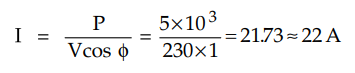
I = 5 × 10³ / 230 × 1 = 21.73
A
This is minimum current drawn to supply
the load. In general, lower is the power factor, higher is the load current and
viceversa. Such higher current results into the following disadvantages :
i) If the fixed amount of power is to be
transmitted or distributed at constant supply voltage then conductor with lower
power factor has to carry more current as the current is inversely proportional
to the power factor if other quantities are constant as seen from the
expression I = P / V cos ϕ This requires greater conductor size which also
increases its cost.
To understand this point clearly, let us
consider an example. Let a particular electrical appliance has a rating of 5 kW
on full load and rated at 230 V. At unity p.f. the current drawn from supply
is,
If the same equipment is operated at 0.7
lagging power factor then current drawn is,
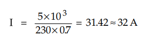
With increase in current at low power
factor, the cross-sectional are of cables is to be selected based on current of
32 A and not on 22 A which would be obviously greater than that required for
unity power factor.
ii) We have seen that,
cos ϕ = Active power / Apparent power =
kW/ kVA
Now kVA is nothing but the rating of
various machines, like alternators, transformers and other swithgear elements.
For low power factor values, to supply fixed active power, large kVA rating
alternators and transformers are required. This makes the equipments larger in
size. Thus overall cost of the system increases.
iii) Large current at lower power factor
causes more copper losses which results into poor efficiency.
iv) Large current with low power factor
causes large voltage drop (IZ) in transmission lines, alternators and
transformers. This reduces the voltage available at supply or receiving end.
Thus the performance of various devices is greatly affected due to poor
regulation. To compensate such voltage drop and to keep the voltage within
permissible limits, extra regulating equipment is necessary which further
increases the cost.
v) The lagging power factor reduces the
power handling capacity as the reactive component of current restricts the
complete utilization of installed capacity.
Thus for a given power, lower is the
power factor, the greater is the cost of generation, transmission and
distribution. Therefore supply authorities encourage the consumers to increase
their power factor.
4. Causes of Low Power Factor
As seen from previous section, lower
value of power factor is undesirable from economic point of view and efficient
operation of the system. Normally the power factor of the supply system is
around 0.8.
The causes of low power factor are
listed below
a) Electric discharge lamps, heating
furnaces in industries, are lamps operate at low lagging factors.
b) Majority of the motors used in
industrial applications or in pumping applications are of induction type either
single or three phase. These motors work at low lagging power factor as their
stator windings takes exciting current from supply which lags behind the
voltage by 90°. The power factor of these motors at no load or light load
condition is very small at 0.2 to 0.3 lagging which improves to 0.8 at full
load condition.
c) The load on the power system is never
constant but keeps on varying all the time. The peak load hours are during
morning and evening while at other time the load is low. During low load
period, the supply voltage being more, the magnetisation current is increased
lowering the power factor.
Review Questions
1. Define power factor. State the causes of low power
factor.
2. Explain the disadvantages of low power factor.
Transmission and Distribution: Unit V: (a) Distribution Systems : Tag: : Power Triangle - Disadvantages - Causes of Low Power Factor - Concept of Power Factor Improvement
Related Topics
Related Subjects

Transmission and Distribution
EE3401 TD 4th Semester EEE Dept | 2021 Regulation | 4th Semester EEE Dept 2021 Regulation