Digital Logic Circuits: Unit III: (b) Analysis & Design of Synchronous Sequential Circuits
Counters
Analysis and Design of Synchronous Sequential Circuits
• A counter is a register capable of counting the number of clock pulses arriving at its clock input.
Counters
•
A counter is a register capable of counting the number of clock pulses arriving
at its clock input.
•
Count represents the number of clock pulses arrived.
•
On arrival of each clock pulse, the counter is incremented by one.
•
In case of down counter, on arrival of each clock pulse, it is decremented by
one.
•
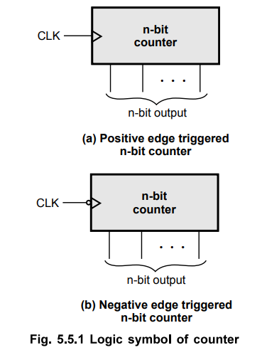
The Fig. 5.5.1 shows the logic symbol of a binary counter.
•
External clock is applied to the clock input of the counter.
•
The counter can be positive edge triggered or negative edge triggered.
•
The n-bit binary counter has n flip-flops and it has 2n distinct
states of outputs.
•
For example, 2-bit counter has 2 flip-flops and it has 4(22)
distinct states : 00, 01, 10 and 11.
•
The 3-bit binary counter has 3 flip-flops and it has 8 (23) distinct
states : 000, 001, 010, 011, 100, 101 110 and 111.
•
The maximum count that the binary counter can count is 2n-\
•
For example, in 2-bit binary counter, the maximum count is 22 -1 = 3
(11 in binary).
•
After reaching the maximum count the counter resets to 0 on arrival of the next
clock pulse and it starts counting again.
Synchronous
Counter :
•
When counter is clocked such that each flip-flop in the counter is triggered at
the same time, the counter is called synchronous counter.
Asynchronous
Counter I Ripple Counter :
•
A binary asynchronous/ripple counter consists of a series connection of
complementing flip-flops, with the output of each flip-flop connected to the
clock input of the next higher-order flip-flop.
•
The flip-flop holding the least significant bit receives the incoming clock
pulses.
•
The Table 5.5.1 shows the comparison between synchronous and asynchronous
counters.

Modulus
of Counter
•
The total number of counts or stable states a counter can indicate is called
'Modulus'.
•
The modulus of a four-stage counter would be 1610, since it is capable of
indicating 00002 to 11112.
•
The term 'modulo' is used to describe the count capability of counters.
•
For example, mod 6 counter goes through states 0 to 5 and mod 4 counter goes
through states 0-3.
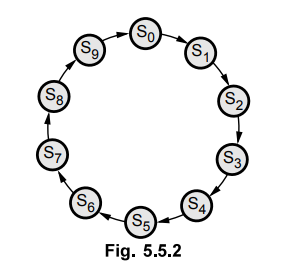
Ex.
5.5.1 Draw the state diagram of MOD-10 counter.
AU
: Dec.-08, Marks 2
Sol.
:
Ex.
5.5.2 Assume that the 5-bit binary counter starts in the 00000 state. What will
be the count after 144 input pulses ?
(144)10
= (1001 0000)2
Since
counter is a 5-bit counter, it resets after 25 = 32 clock pulses.
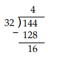
Therefore,
counter resets four times and then it counts remaining 16 clock pulses. Thus,
the count will be (10000)2, i-e., 16 in decimal.
In
general,
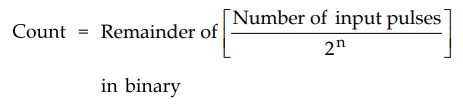
where
n = Number of counter bits
Review Questions
1. What is counter ?
2. State types of counters.
3. Compare synchronous and asynchronous counter.
4. What is MOD counter ?
5. Give comparison between synchronous and asynchronous counters.
Digital Logic Circuits: Unit III: (b) Analysis & Design of Synchronous Sequential Circuits : Tag: : Analysis and Design of Synchronous Sequential Circuits - Counters
Related Topics
Related Subjects

Digital Logic Circuits
EE3302 3rd Semester EEE Dept | 2021 Regulation | 3rd Semester EEE Dept 2021 Regulation