Electron Devices and Circuits: Unit V: (b) Oscillators
Crystal Oscillators
Construction, Equivalent circuit, Principle of Operation, Solved Example Problems
• The crystals are either naturally occurring or synthetically manufactured, exhibiting the piezoelectric effect. The piezoelectric effect means under the influence of the mechanical pressure, the voltage gets generated across the opposite faces of the crystal.
Crystal Oscillators
AU
: Dec.-03, 15, May-11, 12, 14
•
The crystals are either naturally occurring or synthetically manufactured,
exhibiting the piezoelectric effect. The piezoelectric effect means under the
influence of the mechanical pressure, the voltage gets generated across the
opposite faces of the crystal.
•
If the mechanical force is applied in such a way to force the crystal to
vibrate, the a.c. voltage gets generated across it. Conversely, if the crystal
is subjected to a.c. voltage, it vibrates causing mechanical distortion in the
crystal shape.
•
Every crystal has its own resonating frequency depending on its cut. So under
the influence of the mechanical vibrations, the crystal generates an electrical
signal of very constant frequency. The crystal has a greater stability in
holding the constant frequency.
•
The crystal oscillators are preferred when greater frequency stability is
required. Hence the crystals are used in watches, communication transmitters
and receivers etc. The main substances exhibiting the piezoelectric effect are
quartz, Rochelle salt and tourmaline.
•
Quartz is a compromise between the piezoelectric activity of Rochelle salts and
the strength of the tourmaline. Quartz is inexpensive and easily available in
nature and hence very commonly used in the crystal oscillators.
Key
Point : Quartz is widely used for RF oscillators and the
filters.
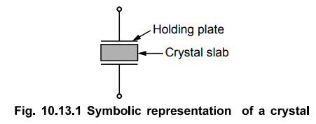
1. Constructional Details
•
The natural shape of a quartz crystal is a hexagonal prism. But for its
practical use, it is cut to the rectangular slab. This slab is then mounted
between the two metal plates.
•
The symbolic representation of such a practical crystal is shown in the Fig.
10.13.1.
•
The metal plates are called holding plates, as they hold the crystal slab in
between them.
2. Equivalent Circuit
•
When the crystal is not vibrating, it is equivalent to a capacitance due to the
mechanical mounting of the crystal. Such a capacitance existing due to the two
metal plates separated by a dielectric like crystal slab, is called mounting
capacitance denoted as CM or C.
• When it is vibrating, there are internal
frictional losses which are denoted by a resistance R. While the mass of the
crystal, which is indication of its inertia is represented by an inductance L.
In vibrating condition, it is having some stiffness, which is represented by a
capacitor C.
•
The mounting capacitance is a shunt capacitance. And hence the overall
equivalent circuit of a crystal can be shown as in the Fig. 10.13.2.

•
RLC forms a resonating circuit. The expression for the resonating frequency fr
is,

•
The Q factor of the crystal is very high, typically 20,000. Value of Q upto 106
also can be achieved.
Hence
√Q2 / 1 + Q2 factor approaches to unity and we get the
resonating frequency as,
fr
= 1 / 2π√LC ...(10.13.3)
•
The crystal frequency is in fact inversely proportional to the thickness of the
crystal.
f
∝ 1/ t where t =
Thickness
•
So to have very high frequencies, thickness of the crystal should be very
small.
•
The crystal has two resonating frequencies, series resonant frequency and
parallel resonant frequency.
3. Series and Parallel Resonance
•
One resonant condition occurs when the reactances of series RLC leg are equal
i.e. XL = XC. This is nothing but the series resonance.
•
The impedance offered by this branch, under resonant condition is minimum which
is resistance R. The series resonance frequency is same as the resonating
frequency given by the equation (10.13.3).
fs
= 1 / 2π√LC ... series resonance ...
(10.13.4)
•
The other resonant condition occurs when the reactances of series resonant leg
equals the reactance of the mounting capacitor CM. This is parallel
resonance or antiresonance condition.
• Under this condition the impedance offered by the crystal to the external circuit is maximum.
• Under parallel resonance, the equivalent capacitance is,

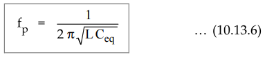
•
Hence the parallel resonating frequency is given by,
•
Generally values of f, and fp are very close to each other and practically it
can be said that there exists only one resonating frequency for a crystal.
•
The higher value of Q is the main advantage of crystal. Due to high Q of a
resonant circuit, it provides very good frequency stability.
•
If we neglect the resistance R, the impedance of the crystal is a reactance jX
which depends on the frequency as,

where ωs = Series resonant frequency
and
ωp = Parallel resonant frequency.
•
The sketch of reactance against frequency is shown in the Fig. 10.13.3.

•
The oscillating frequency lies between w, and op.
4. Crystal Stability
•
The frequency of the crystal tends to change slightly with time due to
temperature, aging etc.
i) Temperature stability: It is defined as the change in the frequency per degree change in the temperature. This is Hz/MHz/C. For 1°C change in the temperature, the frequency changes by 10 to 12 Hz in MHz. This is negligibly small. So for all practical purposes it is treated to be constant. But if this much change is also not acceptable then the crystal is kept in box where temperature is maintained constant, called constant temperature oven or constant temperature box.
ii)
Long term stability : It is basically due to aging of the
crystal material. Aging rates are 2 × 10⁻⁸ per year, for a quartz
crystal. This is also negligibly small.
iii)
Short term stability : In a quartz crystal, the frequency
drift with time is, typically less than 1 part in 106 i.e. 0.0001 %
per day. This is also very small.
Key
Point : Overall crystal has good frequency stability.
Hence it is used in computers, counters, basic timing devices in electronic
wrist watches, etc.
5. Pierce Crystal Oscillator
•
The Colpitts oscillator can be modified by using the crystal to behave as an
inductor. The circuit is called Pierce crystal oscillator.
•
The crystal behaves as an inductor for a frequency slightly higher than the
series resonance frequency fs-
•
The two capacitors C1 C2 required in the tank circuit
along with an inductor are used, as they are used in Colpitts oscillator
circuit.
•
As only inductor gets replaced by the crystal, which behaves as an inductor,
the basic working principle of Pierce crystal oscillator is same as that of
Colpitts oscillator.
•
The practical transistorised pierce crystal oscillator circuit is shown in the
Fig. 10.13.4.

•
The resistances R1, R2, RE provide d.c. bias
while the capacitor CE is emitter bypass capacitor.
•
RFC (Radio Frequency Choke) provides isolation between a.c. and d.c. operation.
CC1 and CC2 are coupling capacitors.
•
The resulting circuit frequency is set by the series resonant frequency of the
crystal.
•
Change in the supply voltages, temperature, transistor parameters have no
effect on the circuit operating conditions and hence good frequency stability
is obtained.
•
The oscillator circuit can be modified by using the internal capacitors of the
transistor used instead of Cj and C2. The separate capacitors Clz C2 are not
required in such circuit. Such circuits using FET and transistor are shown in
the Fig. 10.13.5 (a) and (b).

6. Miller Crystal Oscillator
•
Similar to the modifications in Colpitts oscillator, the Hartley oscillator
circuit can be modified, to get Miller crystal oscillator.
•
In Hartley oscillator circuit, two inductors and one capacitor is required in
the tank circuit. One inductor is replaced by the crystal which acts as an
inductor for the frequencies slightly greater than the series resonant
frequency.
•
The transistorised Miller crystal oscillator circuit is shown in the Fig.
10.13.6.

•
The tuned circuit of L1 and C is offtuned to behave as an inductor i.e. Lj.
•
The crystal behaves as other inductance L2 between base and ground.
•
The internal capacitance of the transistor acts as a capacitor required to
fulfill the elements of the tank circuit.
•
The crystal decides the operating frequency of the oscillator.
•
Due to its low output power, Miller oscillator is not often used in high
frequency applications. It is used in the applications which require an output
of moderate power and good stability at a specific frequency.
•
It is commonly employed in trigger circuits, sawtooth generates, phase control
and timing circuits etc.
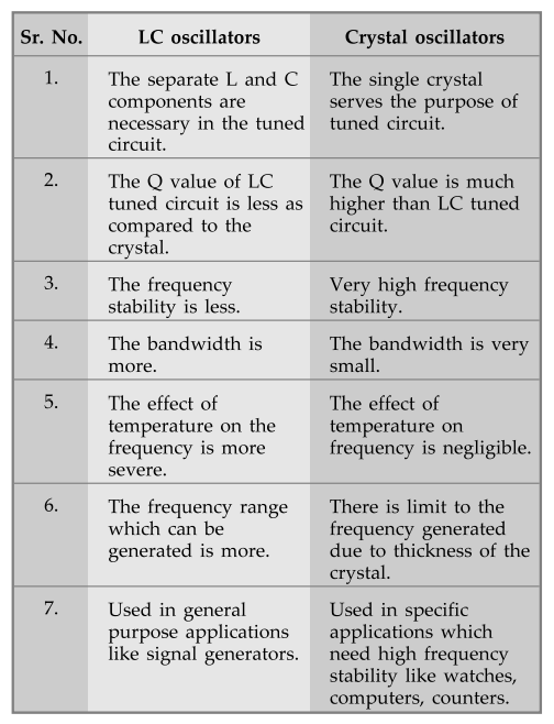
7. Comparison between Crystal and LC Oscillators
Ex.
10.13.1 A crystal has L = 0.33 H, C = 0.065 pF and CM = 1 pF with R
=5.5 KΩ. Find
i)
Series resonant frequency
ii)
Parallel resonant frequency
iii)
By what percent does the parallel resonant frequency exceed the series resonant
frequency ?
iv)
Find the Q factor of the crystal.
Sol.

Ex.
10.13.2 A quartz crystal has L = 3 H, Cs = 0.05 pF, R = 2000 Ω and CM
= 10pF. Calculate the series and parallel resonant frequencies fg
and fp of the crystal.
Sol.
:
L = 3 H, Cs = C = 0.05 pF is series capacitor,

Review Questions
1. What is the principle of oscillation of crystals ? Sketch the
equivalent circuit and impedance-frequency graph of crystals and obtain its
series and parallel resonant frequency.
2. Discuss briefly about the properties of quartz crystal. Draw
the electrical equivalent circuit of the crystal and explain.
3. With a neat diagram, explain the operation of a transistor
Pierce crystal oscillator.
4. Explain working of
Miller type oscillator with circuit. Give two applications.
5. Compare crystal
oscillators with LC oscillators.
6. A crystal L = 0.4
H, C = 0.085 pF and CM PF with R = 5 kΩ.
Find : i) Series resonant frequency
ii) Parallel resonant frequency
iii) By what percent does the parallel resonant frequency exceed
the series resonant frequency ?
iv) Find the Q factor of the crystal.
[Ans.: 0.856 MHz, 0.899 MHz, 430.772]
7. A crystal has the following parameters : L = 0.5 H, Cg = 0.06
pF, Cp = 1 pF and R = 5kQ. Find the series and resonant frequencies and
corresponding Q-factor of the crystal.
[Ans.: 918.8814 kHz, 946.05 kHz, 577.35]
8. A crystal has L = 0.1 H, C = 0.01 pF, R = 10 kΩ and CM
= 1 pF. Find
a. Series resonance frequency b. Q factor
[Ans.: 5.03 MHz, 316.04]
9. What is crystal oscillator ? Draw the circuit diagram and
explain the operation.
AU : May-11,12,14, Marks 12
Electron Devices and Circuits: Unit V: (b) Oscillators : Tag: : Construction, Equivalent circuit, Principle of Operation, Solved Example Problems - Crystal Oscillators
Related Topics
Related Subjects

Electron Devices and Circuits
EC3301 3rd Semester EEE Dept | 2021 Regulation | 3rd Semester EEE Dept 2021 Regulation