Transmission and Distribution: Unit V: (a) Distribution Systems
D.C. Distributor with Concentrated Loads
Concentrated Loads Fed at One End - Concentrated Loads Fed at Both Ends
Questions : 1. Explain the d.c. distributor fed at one end. 2. Explain the d.c. distributor fed at both ends. 3. Draw and explain the current loading and voltage drop diagrams for : a. Concentrated loading on distributor fed at one end b. Concentrated loading on distributor fed at both the ends with equal and unequal voltages. 4. A 2 wire distributor 500 m long is loaded as shown in the Fig. 7.11.16. If the maximum voltage drop allowed is 5 % of the supply voltage, calculate the cross-sectional area of the conductor to be used. Take ρ = 1.73× 10⁻⁸ Ω 5. A two conductor distributor has a length of 700 m and is loaded as shown in the Fig. 7.11.17. The ends A and B are maintained at 250 and 255 V respectively. If the minimum potential allowable at consumer's terminal is 245 V, calculate the diameter of the conductor used. p = 1.7 μ-cm. 6. A 2 wire d.c. distributor AB is fed from both ends. At feeding point A the voltage is 230 V while at B it is 235 V. The total length of distributor is 200 m and loads connected are, 25 A at 50 m from A, 50 A at 75 m from A 30 A at 100 m from A, 40 A at 150 m from A The resistance cf one conductor is 0.3 Ω/km, calculate a. Currents in various sections b. Point of minimum potential c. Value of minimum potential 7. An electric train moves between the substations 8 km apart and draws a constant current of 600 A. The two substations are maintained at a potential of 580 and 575 V respectively. The resistance for both go and return path is 0.05 Ω per km, calculate the minimum potential point and currents supplied by each substation at that instant of minimum potential.
D.C. Distributor with
Concentrated Loads
Dec.-12, May-14, 18
This distributor is further classified
as,
1. Fed at one end 2. Fed at both the
ends
1. Concentrated Loads Fed at One End
The Fig. 7.11.1 shows a distributor with
concentrated loads fed at one end A - A' The loads are connected at the points
a - a ', b - b' and c - c'.
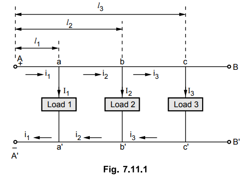
Let l1 , l2
and l3 are the lengths of the sections A - a, A - b and A - c
respectively. The load currents are I1, I2 and I3.
The currents in various sections of the distributor are i1 i2
and i3.
From the Fig. 7.11.1, applying KCL at
various points we can write,
i1 = I1 + I2
+ I3, i2 = I2 + I3 and i3 = I3
The wire A' B' is the return wire of the
distributor.
Let r'
= Resistance per unit length of conductor in Ω
The various voltage drops can be
tabulated as,

Applying KVL to any loop, the load point
voltages can be calculated.
Now r' is the resistance of single
conductor per unit length. And it can be seen that the drops in forward and
return conductors are required to be calculated separately and are equal. In
practice, the resistance of go and return conductors per unit length is assumed
to be r = 2r' and hence two wire distributor can be represented as single wire
for calculation purpose, as shown in the Fig. 7.11.2.

And hence all the drop calculations and
load point voltages remain same as before.
The total drop in the distributor is
= r1 i1 l1
+ r2 i2 l2 (l2 – l1
) + r3 i3 (l3 – l2 )
Many times instead of specifying
resistances per unit length, actual resistances are specified. The resistance
values are of both go and return conductors.
The current loading and voltage drop
diagrams are shown in the Fig. 7.11.3.
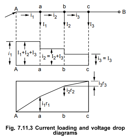
Key Point
It can be seen that the minimum potential will occur at point c which is
farthest from the point A where the distributor is fed at.
2. Concentrated Loads Fed at Both Ends
This type is further classified depending upon the voltage levels at the two ends.
1. Ends fed with equal
voltages and 2. Ends fed with unequal voltages
a. Ends at Equal Voltages
The Fig. 7.11.4 shows this type of
distributor. The ends A and B are maintained at equal voltages.
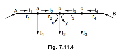
Let r1, r2, r3
and r4 are the go and return resistances of the sections Aa, ab, bc
and cB respectively.
Let point 'b' be the point of minimum
potential.
As we move from point A towards B the
potential goes on decreasing and at point b becomes minimum. All the currents
between section Ab are supplied by point A. After b the voltage goes on
increasing till it becomes feeding voltage at B. All the currents between Band
b are supplied by the point B.
Now the current at minimum potential
point b is supplied by both. Let x be supplied by point A while y be supplied
by point B. It is obvious that y = I2 - x.
As both the points A and B are
maintained at same voltage, drop in section Aa must be equal to drop in section
Bb.
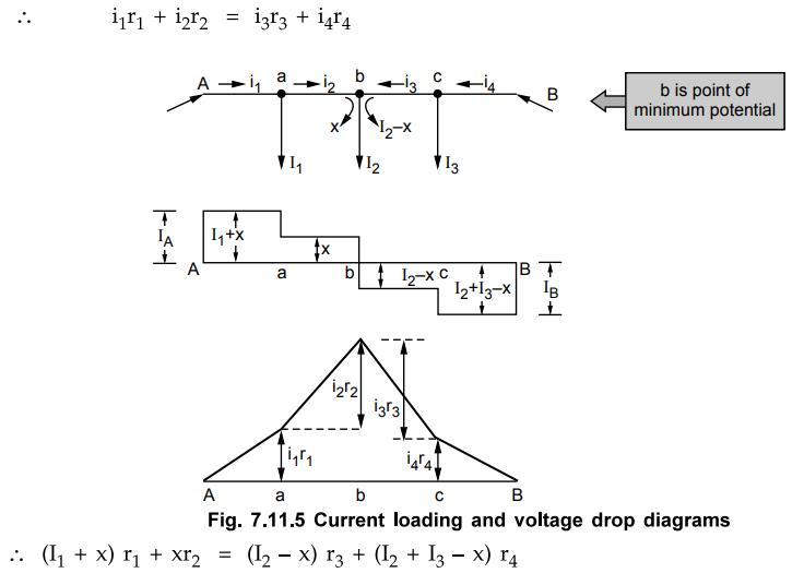
Thus knowing all the currents, x can be
calculated and all the voltage drops can be obtained.
The Fig. 7.11.5 shows the current
loading and voltage drop diagrams.
Key Point
The load point where the currents are coming from both the sides of the
distributor is the point of minimum potential.
b. Ends at Unequal Voltages
The Fig. 7.11.6 shows this type of
distributor. The ends A and B are maintained at different voltages.
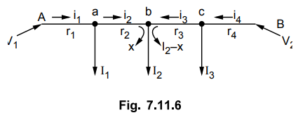
Let the resistances of the sections Aa,
ab, bc and cB are r1, 12, 13 and 14 respectively. Let point 'b' is the point of
minimum potential.
In this case also the point b is fed by both the points A and B. The current from point A is x while from B it is I2 - x. Now we can write the equation as,
Voltage drop between A and B = Voltage
drop over AB
If voltage of A is V1 and is
greater than voltage of B which is V2 then,
V1
- V2 = Drops in all the sections of AB
The same equation can be written as,
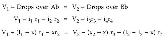
Solving this equation, as V1
and V2 are known, x can be obtained.
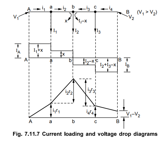
The Fig. 7.11.7 shows the current
loading and voltage drop diagrams.
Example 7.11.1
A two wire d.c. distributor system is 3 km long and it supplies loads of 200
A, 100 A, 75 A and 50 A at 800 m, 1200 m, 2000 m and 3000 m from the feeding
point A. Each conductor has go and return resistance of 0.004 Ω per 100 m.
Calculate the voltage at each load point if voltage at feeding point is 250 V.
Solution :
The distributor is shown in the Fig. 7.11.8.

These are the voltage at the various
load points a, b, c and B.
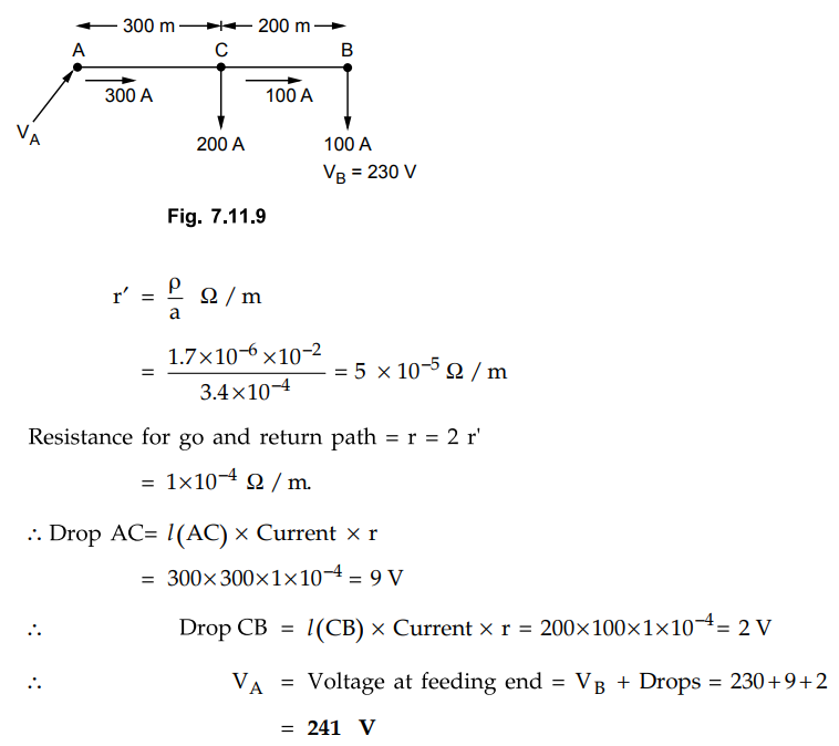
Example 7.11.2
A two wire D.C. distributor 500 m long is fed at one end. The cross
sectional area of each conductor is 3.4 cm and resistivity of copper is 1.7
pcm. The distributor supplies 200 A at distance of 300 m from the feeding point
and 100 A at the terminal. Calculate the voltage at the feeding end if the
voltage at the terminal is to be 230 V.
Solution :
The distributor is shown in the Fig. 7.11.9.
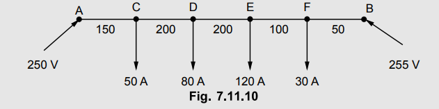
Example 7.11.3
A two conductor distributor has a length of 700 m and is loaded as shown in
Fig. 7.11.10, the distance being represented in meters. The ends A and B are
maintained at 250 V and 255 V respectively. If the minimum potential allowable
at consumer's terminal is 245 V, calculate the diameter of the conductor used.
Resistivity is 1.7 micro ohm-cm.
Solution :
The distributor is shown in the Fig. 7.11.10 (a). Let r be the resistance for
the both go and return per unit length.
Let D be the point of minimum potential. So current of x A is supplied from
point A while 80 - x is supplied from point E as shown in the Fig. 7.11.10 (a).

The current distribution is as shown in
the Fig. 7.11.10 (b).

The allowable
voltage is 245 V hencemaximum permissible 250 Vvoltage drop is 250 - 245 = 5 V
at D from A which is point of minimum potential.

Example 7.11.4
Four lines A, B, C and D are connected to a common point O. Resistances of
AO, BO, CO and DO are respectively 1, 2, 3 and 4 Ω both go and return and
feeding points A, B, C and D are maintained at 230, 250, 240 and 220 V
respectively. Find the potential of common point O assuming no load is tapped
from there.
Solution :
The arrangement is shown in the Fig. 7.11.11.
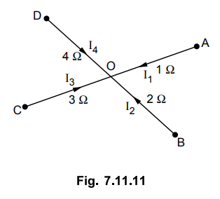
Applying KCL at node O,

where VO is voltage of point
O and no load is tapped from O so summation of all currents entering is zero,
no current going away from O. Substituting values VA, VB,
VC and VD we get,
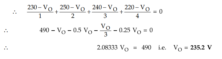
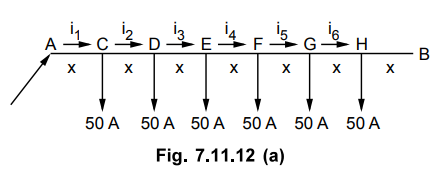
Example 7.11.5
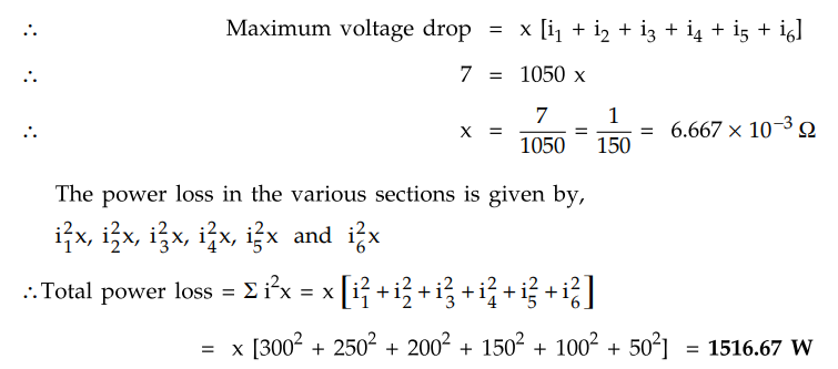
A 2 wire distributor AB is fed at A and supplies six concentrated loads each
of 50 A at C, D, E, F, G and H as shown in the Fig. 7.11.12. What must be the
resistance of each section so that maximum voltage drop for any consumer does
not exceed 7 V ? Also calculate the total power loss with this resistance.
Assume that the loads are spaced at equal distances.

Solution : The various currents are shown in the Fig. 7.11.12 (a).
And let x be the resistance of each
section of conductor.
As the loads are equispaced, l(AC)
= l (CD) = l (DE) = l (EF) = l (FG) = l (GH)
Hence resistances of all the sections
are equal.
Now, i6
= 50 A ... no current after H
I5 = 50 + 50 = 100 A
I4 = 100 + 50 = 150 A and i3
= 150 + 50 = 200 A
I2 = 200 + 50 = 250 A and i1
= 250 + 50 = 300 A
The voltage drops in the various
sections are i1x, i2x, i3x, i4x, i5x,
and i6x
The maximum voltage drop will be at
point H which will be the summation of all the drops in the section AC, CD, DE,
EF, FG and GH.
Example 7.11.6
A distributor AF is fed at both ends at the same voltage of 250 V. The
length of the distributor is 200 m and the loads are tapped off as follows : 50
A at 50 m from the end A, 50 A at 75 m from A, 30 A at 100 m from A, and 25 A
at 150 m from A. Calculate (a) the minimum potential and (b) the voltage at
each load point. The resistance per 100 metres of the conductor for go and
return is 0.08 Ω.
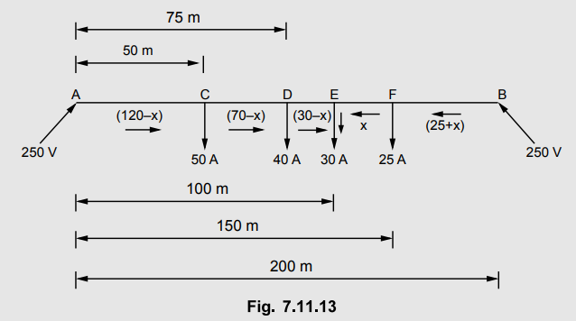
Solution :
Let r be the resistance for both 90 and return per unit length. Let E be the
point of minimum potential. Let x amperes be the current supplied at E from B.
Now as two ends are at equal voltages,
Drop (A - E) - Drop (B - E)

Example 7.11.7 An
electric train taking a constant current of 600 amps moves on a section of
line between two substations 8 km apart and maintained at 575 and 590 volts
respectively. The track resistance is 0.04 per km both go and return. Find the
point of minimum potential along the track and currents supplied by two
substations at that instant.
AU : May-14, Marks 8
Solution : The arrangement is shown in the Fig. 7.11.14.

Let point P be the point of
minimum potential at a distance x from A. Let current fed from feeding point A
be IA hence current drawn from B is 600 - IA

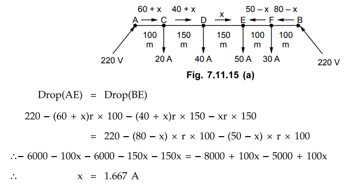
Example 7.11.8
A 2-wire d.c. street mains AB, 600 m long is fed from both ends at 220 V.
Loads of 20 A, 40 A, 50 A and 30 A are tapped at distances of 100 m, 250 m, 400
m and 500 m from the end A respectively. If the area of X-section of
distributor conductor is 1 square centimeter, find the minimum consumer
voltage. Take ρ = 1.7 × 10⁻⁶ ohm-cm.
AU : May-18, Marks 15
Solution :
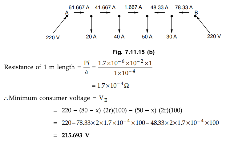
Let E be the point of minimum potential. At 'E' let x A is supplied from point
A while (50 - x) A is supplied from point B.
The actual distribution of currents in
various sections is shown in the Fig. 7.11.15 (b).
Review Questions
1. Explain the d.c. distributor fed at one end.
2. Explain the d.c. distributor fed at both ends.
3. Draw and explain the current loading and voltage drop diagrams
for :
a. Concentrated loading on distributor fed at one end
b. Concentrated loading on distributor fed at both the ends with
equal and unequal voltages.
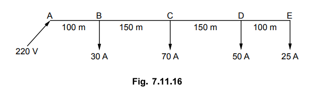
4. A 2 wire distributor 500 m long is loaded as shown in the Fig.
7.11.16. If the maximum voltage drop allowed is 5 % of the supply voltage,
calculate the cross-sectional area of the conductor to be used. Take ρ = 1.73×
10-8 Ω
[Ans.: 1.667 ×10⁻⁴ m2]
5. A two conductor distributor has a length of 700 m and is loaded
as shown in the Fig. 7.11.17. The ends A and B are maintained at 250 and 255 V
respectively. If the minimum potential allowable at consumer's terminal is 245
V, calculate the diameter of the conductor used. p = 1.7 μ-cm.
[Ans. : 0.2204 cm]

6. A 2 wire d.c. distributor AB is fed from both ends. At feeding point A the voltage is 230 V while at B it is 235 V. The total length of distributor is 200 m and loads connected are,
25 A at 50 m from A, 50 A at 75 m from A
30 A at 100 m from A, 40 A at 150 m from A
The resistance cf one conductor is 0.3 Ω/km, calculate
a. Currents in various sections b. Point of minimum potential c.
Value of minimum potential
[Ans.: Point of minimum potential at 50 A load, 228.875 V]
7. An electric train moves between the substations 8 km apart and
draws a constant current of 600 A. The two substations are maintained at a
potential of 580 and 575 V respectively. The resistance for both go and return
path is 0.05 Ω per km, calculate the minimum potential point and currents
supplied by each substation at that instant of minimum potential.
[Ans.: 4.0833 km, 306.25 A, 293.75 A]
8. A 2 wire d.c. ring distributor is fed at A with 220 V. The
various loads are 10 A at B, 20 A at C, 30 A at D and 10 A at E. The
resistances of the sections AB, BC, DC, DE and EA are 0.1 Ω, 0.05 Ω, 0.01 Ω,
0.025 Ω and 0.075 Ω respectively.
Determine, a. Point of minimum potential b. Current in each
section.
[Ans.: Point C, 29.04 A, 19.04 A, 0.96 A, 30.96 A and 40.96 A]
Transmission and Distribution: Unit V: (a) Distribution Systems : Tag: : Concentrated Loads Fed at One End - Concentrated Loads Fed at Both Ends - D.C. Distributor with Concentrated Loads
Related Topics
Related Subjects

Transmission and Distribution
EE3401 TD 4th Semester EEE Dept | 2021 Regulation | 4th Semester EEE Dept 2021 Regulation