Transmission and Distribution: Unit V: (a) Distribution Systems
D.C. Distributor with Uniformly Distributed Load
Load Fed at Both Ends - Load Fed at One End
Questions : 1. Prove that the shape of voltage drop diagram for a distributor, with uniform loading of 1 A/m fed at one end, is a parabola. Derive suitable expressions, draw current loading diagram and voltage drop diagram for uniformly loaded distributor of length f fed at one end. How is power loss in the whole distributor computed ? 3. Prove that the maximum drop for the distributor with distributed loading fed at both ends with equal voltages is IR/8 where I is total current and R is total resistance of both go and return. 4. Derive the expressions for the power loss in the distributor which is uniformly loaded with a) Ped at one end b) Fed at both ends with equal voltages. 5. Consider a distributor loaded with uniform loading of i ampere per meter run and are fed from two feeding points at different voltages. Find the point of minimum potential occurrence in the distributor. 6. A 2 wire d.c. distributor 200 m long is uniformly loaded with 2 A/m. Resistance of single wire is 0.3 Ω/km. If the distributor is fed at one end, calculate : 1. The voltage drop upto a distance of 150 m from the feeding point. 2. The maximum voltage drop. 7. Calculate the voltage drop at a distance of 200 m of a 300 m long distributor uniformly loaded at a rate cf 0.75 A/m. a. When it is fed from one end at 250 V b. When it is fed from both ends at 250 V The resistance of each conductor for both go and return per metre is 0.00018 Ω. Determine the power loss in each case.8. A 800 m, 2 wire d.c. distributor AB is fed from both ends is uniformly loaded at the rate of 1.25 A/m run. Calculate the voltages at the feeding points A and B if the minimum potential of 220 V occurs at point C at a distance of 450 m from the end A. The resistance cf each conductor is 0.05 Ω/km.
D.C. Distributor with
Uniformly Distributed Load
This type of distributor is also
classified as,
1. Distributor fed at one end and 2.
Distributor fed at both the ends
1. Distributor Load Fed at One End
The Fig. 7.12.1 shows the single line diagram
of uniformly distributed load on two wire distributor, fed at one end.

The distributed load is of i amperes per
metre.
This indicates that at every metre
length i amperes load is supplied through tapping on the distributor.
Let l
= Length of the distributor
r = Resistance per unit length in Ω
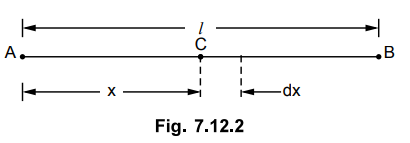
In such case, total voltage drop is to be obtained by considering a point C at a distance x from feeding end A. This is shown in the Fig. 7.12.2.
The current tapped at point C is
= Total current – Current up to point
'C' = i × l – i × x = i (l - x)
Consider an elementary length dx near
point C. Its resistance is r dx.
Hence the voltage drop over the length
dx is,
dV = i (l - x) r dx
Thus total voltage drop upto point C is,

This is the equation of parabola.
Thus the voltage drop upto point B can
be obtained by putting x = l.

where I = Total current fed at point A
R = Total resistance of the distributor
From this one important observation can
be noted as :
Key Point
In a uniformly distributed load on the distributor fed at one end, the total
voltage drop is equal to that produced by the whole of the load assumed to be
concentrated at the middle point.
This fact can be used to simplify the
complicated load calculations.
The Fig. 7.12.3 shows current loading
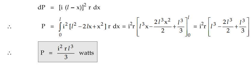
and voltage drop diagrams.

The power loss i.e. I2 R loss
can be obtained from the elementary length dx.
The current at any point C at distance x
is i (l - x). Hence the power loss over the elementary length dx is,
2. Distributed Load Fed at Both Ends
This is type is further classified as,
1. Ends maintained at equal voltages and
2. Ends maintained at unequal voltages
a. Ends at Equal Voltages
The Fig. 7.12.4 shows a distributor of
length I with uniform load of i amperes per metre. The resistance of the
conductor is r ohms per metre. It is fed at the points A and B which are
maintained at equal voltages.

The total current to be supplied is il
amperes.
As two end voltages are equal, each end
will supply half the required current i.e. il/2
The point of minimum potential will be
at a distance of l/2 from either end i.e. midpoint.
Consider a point C at a distance x metres
from feeding end A as shown in the Fig. 7.12.5.

The current entering at feeding end A is
(il/2).
Hence the current at point C can be
written as,
Current at C = il/2 - ix = i
(1/2-x)
Consider an elementary length dx near C
whose resistance is rdx. So voltage drop over length dx is,
dv = i (l/2 – x) r dx
Hence voltage drop upto point C is,

Now maximum voltage drop is at midpoint
i.e. x = 1/2 as the midpoint is the point of minimum potential.

where I is total current and R is the
total resistance.
It is 1/4th of the drop in case of
distributed load distributor fed at one end. The point of minimum potential is
the farthest end from feeding end in case of distributor fed at one end while
in this case, it is midpoint of the length of the distributor.
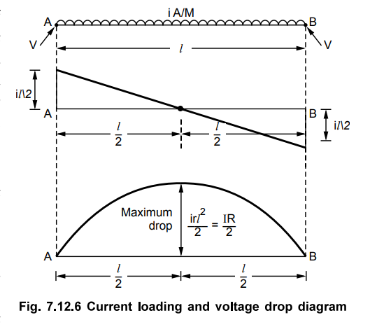
The Fig. 7.12.6 shows current loading
and voltage drop diagrams.
The power loss in this case also can be
obtained from the power loss over elementary length dx.
The current at any point C at distance x
is i (l/2 – x)
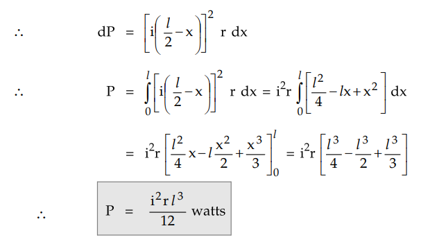
This is power loss over the entire
length I of the distributor. Hence power loss in half length is half of the
total power loss which is i2r l3 / 24 watts.
b. Ends at Unequal Voltages
The Fig. 7.12.7 shows the uniformly
distributed load on the distributor of length l. The load is i amperes/m
while the distributor is fed at both the ends which are maintained at different
voltages.

To find the location of point of minimum
potential :
Let point C be the point of minimum
potential which is at a distance x from feeding point A.
The current supplied by the feeding
point A is ix. While the current supplied by the feeding point B is i (l
- x).
Now, V1 - Drop in section AC
= V2 - Drop in section BC.
Let r be the resistance per metre
length.
In case of distributed load the drop is
given by irl2 / 2 for a length of l. Considering section
AC as separate section fed at one end the drop in section AC can be written as,

Knowing V1, V2, i,
r and l, the above equation can be solved for x which gives the point of
minimum potential.
Example 7.12.1
A 2 wire d.c. distributor 300 m long is
uniformly loaded with a load of 1 AJm. The resistance of single wire is 0.4
Q/km. If the distributor is fed at one end, calculate:
1. The voltage drop upto a distance of
225 m from the feeding point.
2. The maximum voltage drop.
Solution :
The current loading is i = 1 A/m, l = 300
r = 0.4 Ω/km of single wire
2 × 0.4 / 1000 = 8 × 10⁻⁴
Ω/m ... go and return path
The voltage drop upto any point at
distance x from the feeding end is given by,

Example 7.12.2
A two core cable is 500 m long, the total resistance go and return is 0.075
Ω. The cable is uniformly loaded with 2 AJm load and is fed from both the ends
at 260 V. Prove that the minimum potential point occurs at the midpoint of the
cable and calculate value of minimum potential and total power loss in the
cable.
Solution :
The cable is shown in the Fig. 7.12.8.

Let point of minimum potential is at C,
at distance x from A.
Load current due to length dx = i dx
The resistance of the section AC = rx

Example 7.12.3 A
800 m long, two wire DC distributor fed from both ends, is loaded uniformly at
the rate of 1.2 AJm run. If the resistance of the distributor is 0.1 Ω / km (go
and return) and feed points are maintained at 245 V and 240 V respectively,
calculate the minimum voltage, its points of occurrence and current supplied
from two feeding points.
Solution : The distributer is shown in the Fig. 7.12.9.

Let minimum potential occurs at
point C at a distance x from end A.

Thus point of minimum potential is
426.0416 m from point A.
 This is the value of minimum potential.
Current supplied by A = ix = 1.2 ×
426.0416 = 511.25 A
A Current supplied by B = i(l -
x) = 1.2 × 373.9584 = 448.75 A
Example 7.12.4
A 2 wire distributor is uniformly
loaded at the rate 1.2 AJm and is fed at both the ends. The point of minimum
potential occurs at 575 m from end A and the minimum potential is 225 V. If
length of the distributor is 1 km, calculate the voltages at the feeding ends A
and B. The resistance of each conductor is 0.04 Ω/km.
Solution :
The distributor is shown in the Fig. 7.12.10.

Example 7.12.5
A distributor 500 m long has a total resistance of 0.05 Q both go and return path.
The distributor is loaded with concentrated loads of 80 A, 70 A, 50 A and 100 A
at a distance of 100 m, 200 m, 250 m, 400 m from feeding end A respectively. In
addition to this there is uniformly distributed load of 0.5 A/m on the
distributor. If both ends A and B are maintained at 220 V, calculate the point
of minimum potential, the value of minimum potential and current supplied by
each end.
Solution : The
distributor is shown in the Fig. 7.12.11(a).

Let point E be the point of minimum
potential hence the current distribution is,

The drop due to uniformly distributed
load is given by irx2 / 2 where x is distance of point upto which
drop is required.
Drop due to concentrated + distributed
load in AE
= Drop due to concentrated + distributed
load in BE

Thus point E is the point of minimum
potential.
Total current due to distributed load =
i × l - 0.5 × 500 = 250 A
Half of this will be supplied by each
end.

Value of minimum potential is, VE
= VA - Drop in section AE
Drop in AE due to concentrated loads
= 151 × 0.01 + 71 × 0.01 + 1 × 0.005 =
2.225 V
Drop in AE due to distributed load

Example 7.12.6
A 2 wire distributor AB is 450 m long and is fed at both ends at 420 V. The
distributor is loaded as shown in the Fig. 7.12.12.

The resistance for both go and return is
0.1 Ω per 500 m length. Find the point of minimum potential and its potential.
Solution:
Let D be the point of minimum potential. So the current distribution is as
shown in the Fig. 7.12.12 (a).
Drop in section AD = (100 + x) × 60 r +
(x × 40 × r)
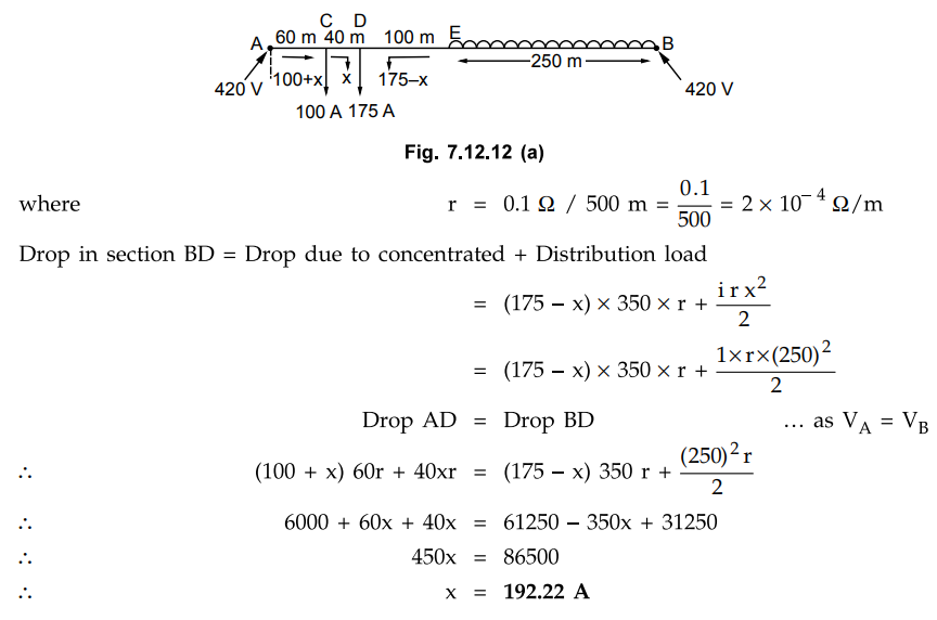
The current required at point D = 175 A
but 192.22 A is supplied by the end A.
The remaining current 192.22 - 175 =
17.22 A is supplied to the distributed load.
So length covered by current from A of
distributed load is 17.22 A / 1A/m = 17.22 m.
Hence the point of minimum potential
from end A is
= 60 + 40 + 100 + 17.22 = 217.22 m
The drop of potential up to point of
minimum potential from end B = iry2 / 2
where y = Distance of point of minimum
potential from B
= 450 - 217.22 = 232.78 m

The drop of potential up to point of
minimum potential from end A

This is same as obtained above. This is
cross check.
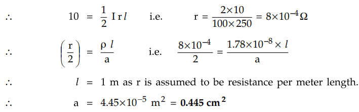
Example 7.12.7 A
uniform two wire DC distributor 250 m long is loaded with 0.4 A/m and is fed at
one end. If the maximum permissible voltage drop is not to exceed 10 V, find
the cross sectional area of the distributor conductor. Take ρ = 1.78 × 10⁻⁸
Ωm.
AU : Dec.-15, Marks 8
Solution :
Current entering the distributer = i x I - 0.4 × 250 = 100 A
Maximum permissible voltage drop = 10 V
Let r Ω be the resistance per metre
length of the distributer (both wires i.e. go and return)
Maximum voltage drop = 1 / 2 IR
Review Questions
1. Prove that the shape of voltage drop diagram for a distributor, with uniform loading of 1 A/m fed at one end, is a parabola.
Derive suitable expressions, draw current loading diagram and
voltage drop diagram for uniformly loaded distributor of length f fed at one end.
How is power loss in the whole distributor computed ?
3. Prove that the maximum drop for the distributor with distributed
loading fed at both ends with equal voltages is IR/8 where I is total current
and R is total resistance of both go and return.
4. Derive the expressions for the power loss in the distributor
which is uniformly loaded with a) Ped at one end b) Fed at both ends with equal
voltages.
5. Consider a distributor loaded with uniform loading of i ampere
per meter run and are fed from two feeding points at different voltages. Find
the point of minimum potential occurrence in the distributor.
6. A 2 wire d.c. distributor 200 m long is uniformly loaded with 2
A/m. Resistance of single wire is 0.3 Ω/km. If the distributor is fed at one
end, calculate :
1. The voltage drop upto a distance of 150 m from the feeding
point.
2. The maximum voltage drop.
[Ans.: 22.5 V, 24 V]
7. Calculate the voltage drop at a distance of 200 m of a 300 m
long distributor uniformly loaded at a rate cf 0.75 A/m.
a. When it is fed from one end at 250 V b. When it is fed from both
ends at 250 V
The resistance of each conductor for both go and return per metre is
0.00018 Ω. Determine the power loss in each case.
[Ans : a) 244.6 V, 1.367 kVV b) 249.325 V, 227.83 W]
8. A 800 m, 2 wire d.c. distributor AB is fed from both ends is uniformly
loaded at the rate of 1.25 A/m run. Calculate the voltages at the feeding
points A and B if the minimum potential of 220 V occurs at point C at a
distance of 450 m from the end A. The resistance cf each conductor is 0.05 Ω/km.
[Ans.: 232.65 V, 227.65 V]
Transmission and Distribution: Unit V: (a) Distribution Systems : Tag: : Load Fed at Both Ends - Load Fed at One End - D.C. Distributor with Uniformly Distributed Load
Related Topics
Related Subjects

Transmission and Distribution
EE3401 TD 4th Semester EEE Dept | 2021 Regulation | 4th Semester EEE Dept 2021 Regulation