Transmission and Distribution: Unit V: (a) Distribution Systems
D.C. Three Wire System
Current Distribution of
Questions : 1. Explain different methods to obtain 3-wire DC system. 2. In the 3 wire d.c. distributor shown in the Fig. 7.8.8 the resistances of various sections shown are in ohms. Calculate the voltages at various load points.3. A load supplied on a 3 wire d.c. system takes a current of 50 A on the positive side and 40 A on the negative side. The resistance of each outer wire is 0.1 Ω and the cross-section of the middle wire is one half that of the outer. If the system is supplied at 500 / 250 V, find the voltage at the load end between each outer and middle wire.
D.C. Three Wire System
It is known that higher the voltage
level, lower are the transmission losses. But in case of d.c. distribution,
level can not be increased readily like a.c. Using rotating machinery, the d.c.
voltage level can be increased but the method is too expensive. The d.c. three
wire system can be used to double the transmission voltage, without increasing
the voltage between either conductor and earth. The higher voltage demand also
can be satisfied using d.c. three wire distribution system.
In this system, two generators are
connected in series, each is generating a voltage of V volts. The common point
is neutral from where neutral wire is rim. The voltage V of each generator is
with respect to neutral which is earthed. Thus the voltage between each line
and neutral is V volts while between the lines it is 2 V volts. Thus the
consumers demanding higher voltage are connected to the two lines while the
consumers demanding less voltage for lighting load are connected between any
one line and neutral. The Fig. 7.8.1 shows the d.c. three wire distribution
system.

The light loads, domestic loads are connected between any of the two lines and neutral while the d.c. motor loads requiring higher voltage are connected between the lines. The neutral is earthed.
The symbolic representation of three wire d.c. system is shown in the Fig. 7.8.2.

The Fig. 7.8.2 shows the current
distribution in the system. The one line carries current I1 while
the other line carries current I2. When the load is balanced, that
is loads connected on either sides of the neutral wire are equal, then the
neutral current is zero. And under such condition, the potential of the neutral
wire is exactly half of the potential between the two outer lines. Thus the
positive outer wire is at V volts above the neutral while the negative outer
wire is at V volts below the neutral.
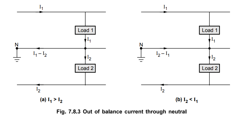
If the loads are not balanced then the
neutral carries the current. This current is the difference between the two
line currents I1 and I2 and is called out of balance
current. If the load on the positive line i.e. Ix is greater than I2
then neutral wire carries current equal to I1 - I2. If
the load on the negative line is greater i.e. I2 is greater than Ij
then the neutral wire carries current equal to I2 - Ip This is shown
in the Fig. 7.8.3 (a) and (b). The direction of I1 - I2
is from load end to supply end while the direction of I2 – I1
is from supply end to load end.
In any of the two cases of out of
balance current conditions, the neutral potential will not remain half of that
between the two lines.
Instead of using two generators in
series, a single generator having twice the line to neutral voltage rating also
can be used.
This is shown in the Fig. 7.8.4.
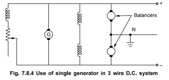
In such system, two small d.c. machines
are connected across the lines in series which are mechanically coupled to a
common shaft, these are called balancers.
Normally when the load is balanced,
machines work as the d.c. motors. In case of any out of balance current through
neutral then the machine connected to lightly loaded side acts as motor while
that connected to heavily loaded side acts as generator. And the energy is
transferred from lightly loaded side to heavily loaded side as machine as motor
drives the machine as generator. Thus the imbalance is compensated.
The perfect balancing can not be
obtained because the working of the balancers are based on slight unbalancing
of the voltages on the two sides.
1. Current Distribution in 3 Wire D.C. System
The Fig. 7.8.5 shows 400/200 V, 3 wire
d.c. distribution system. The total current distribution can be understood by
taking concrete values of load currents. The motor load connected across the
lines demand 175 A while other loads requiring less voltage, are connected
between line and neutral, on both the sides of neutral. The two loads connected
between positive line and neutral take 35 and 25 A current respectively while
the two loads connected between negative line and neutral take 50 A current
each.
Applying Kirchhoff's current law at
various nodes, the currents in all the sections can be determined as shown in
the Fig. 7.8.5.
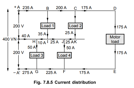
It can be seen that for the selected
values, I1 = 235 A while I2 = 275 A.
Thus I2 – I1 = 275
- 235 A = 40 A current flows at the neutral point and its direction is from neutral
end towards load end. Thus knowing currents in all the sections and resistances
of all the sections, the voltage across any load can be determined by applying
Kirchhoff's voltage law to the appropriate loop. Such a voltage is called load
point voltage. While applying Kirchhoff's voltage law, care must be taken to
consider the sign of the voltage drop correctly. If the potential across two
points is traced from positive to negative as a drop then it must be taken as
negative while if the potential is traced from negative to positive i.e. as a
rise it must be taken as positive.
Example 7.8.1
A 3 wire d.c. system takes a current
of 50 A on positive side and 45 A on negative side. The resistance of each
outer is 0.0004 Ω per metre while the cross-section of middle wire is half of
that of each outer. If the voltage between each outer and middle wire is
maintained at 220 V at the feeding end, calculate the voltage at the distant
load end between each outer and middle wire. The 3 wires are of 100 m length.
Solution :
The system is shown in the Fig. 7.8.6.

Now I1 = 50 A and I2
= 45 A hence current through neutral wire is I1 – I2 = 5
A from load side to supply side.

Applying KVL to the loop ABCNA and
taking potential drop as - ve and rise as + ve we can write,
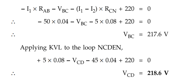
Applying KVL to the loop NCDEN,
+ 5 × 0.08 - VCD - 45 × 0.04
+ 220 = 0
VCD = 218.6 V
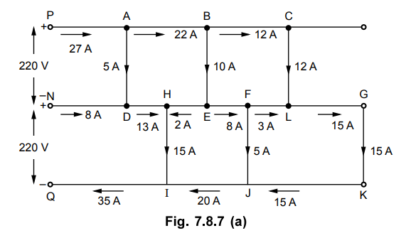
Example 7.8.2
A 3 wire d.c. distributor is fed at one end at 220 V between wires and
middle wire as shown in Fig. 7.8.7. The numbers between section indicate the
resistance of the respective section. Calculate the voltage between middle wire
and outer at each load point.
AU : Dec.-11, Marks 16

Solution :
By applying KCL, the currents in various sections can be obtained. The total
current distribution is shown in the Fig. 7.8.7 (a).
The voltage drops in the various
sections are,
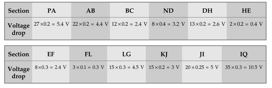
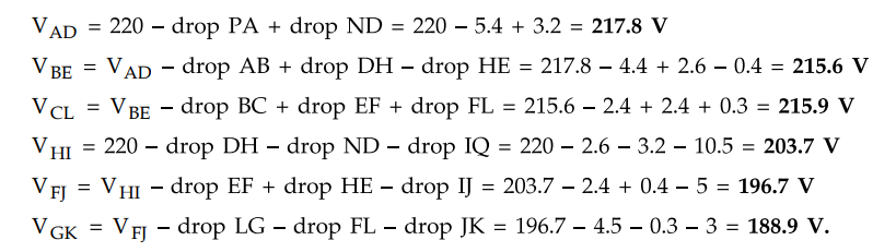
Applying KVL to the various loops,
Review Questions
1. Explain different methods to obtain 3-wire DC system.
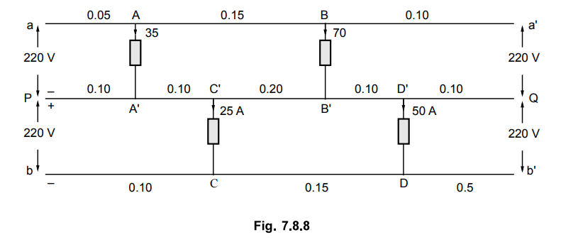
2. In the 3 wire d.c. distributor shown in the Fig. 7.8.8 the
resistances of various sections shown are in ohms. Calculate the voltages at
various load points.
[Ans.: 215.98 volts, 206.52 volts, 219.74 volts, 217.62 volts]
3. A load supplied on a 3 wire d.c. system takes a current of 50 A on the positive side and 40 A on the negative side. The resistance of each outer wire is 0.1 Ω and the cross-section of the middle wire is one half that of the outer. If the system is supplied at 500 / 250 V, find the voltage at the load end between each outer and middle wire.
[Ans.: 243 V, 248 V]
Transmission and Distribution: Unit V: (a) Distribution Systems : Tag: : Current Distribution of - D.C. Three Wire System
Related Topics
Related Subjects

Transmission and Distribution
EE3401 TD 4th Semester EEE Dept | 2021 Regulation | 4th Semester EEE Dept 2021 Regulation