Digital Logic Circuits: Unit III: (b) Analysis & Design of Synchronous Sequential Circuits
Design of Synchronous Counters
1. Determine the number of flip-flops needed. If n represents number of flip-flops 2n ≥ number of states in the counter.
Design of Synchronous Counters
AU:
Dec.-03, 07, 09, 11, 12, 15, 16, May-03, 04, 05, 10, 11, 15
1.
Determine the number of flip-flops needed. If n represents number of flip-flops
2n ≥ number of states in the counter.
2.
Choose the type of flip-flops to be used.
3.
Using excitation table for selected flip-flop determine the excitation table
for the counter.
4.
Use K-map or any other simplification method to derive the flip-flop input
functions.
5.
Draw the logic diagram.
Ex.
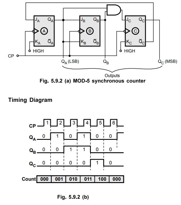
5.9.1 Design a MOD-5 synchronous counter using JK flip-flops and implement it.
Also draw the timing diagram.
AU
May-15, Marks 8
Sol.
:
Step
1:
Determine the number of flip-flop needed
Flip-flops
required are
Here
2n
≥ N
N
= 5
n
= 3 i.e. three flip-flops are required.
Step
2
: Type of flip-flop to be used : JK
Step
3 : Determine
the excitation table for the counter.

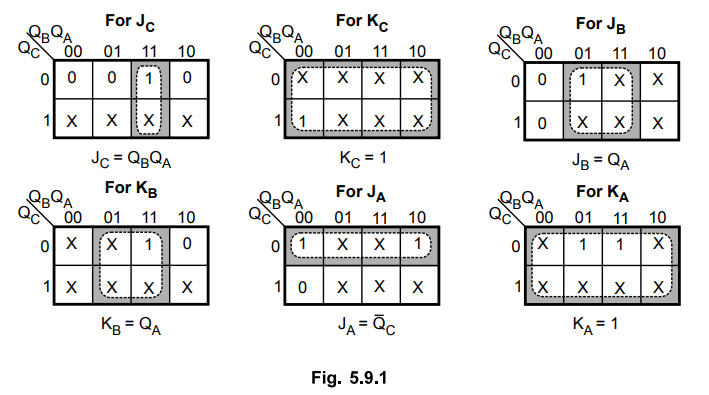
Step 4 : K-Map Simplification
Step
5 :
Draw the logic diagram
Ex.
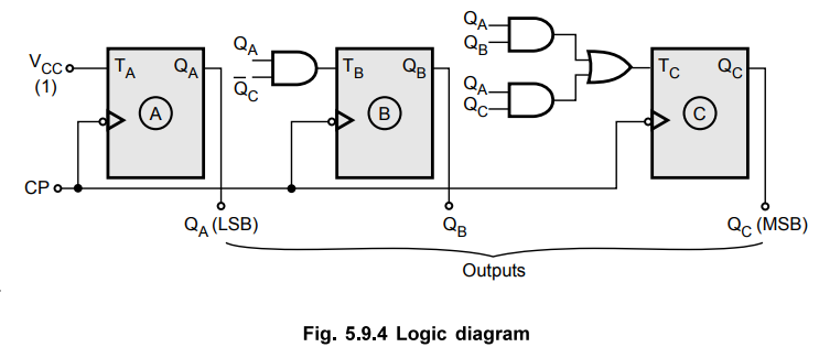
5.9.2 Design divide by 6 counter using T-flip-flops. Write state table and
reduce the expression using K-map.
Sol.
:
Step
1 :
Determine the number of flip-flops needed.
For
designing mod 6 counter using the formula
2n
≥ N
Here N = 6 n = 3 i.e. 3 flip-flops are required.
Step
2 :
Type of flip-flops to be used : T
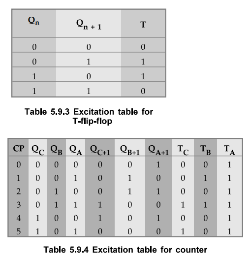
Step
3 :
Determine the excitation table for counter.
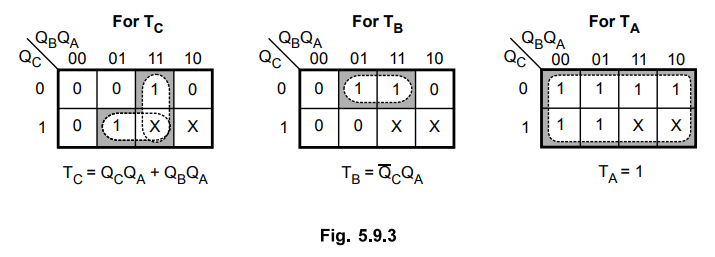
Step 4 : K-map
simplification.
Step 5 : Draw the logic
diagram.
Ex.
5.9.3 Using positive edge triggering SR flip-flops design a counter which
counts in the following sequence : 000, 111, 110, 101, 100, Oil, 010, 001, 000,
....
Sol.
:
Step
1 :
Determine the number of flip-flops needed
We
know that 2n ≥ N. Here, N = 8 n = 3
Step
2 :
Type of flip-flop to be used : SR
Step
3 :
Determine the excitation table for counter.
Here,
the next state for each present state is written according to given sequence.
For example, the next state for the present state 000 is 111.

Step
4 :
K-map simplification.
Step
5 :
Draw logic diagram

Ex.
5.9.4 Design a synchronous decade counter using D flip-flop.
Sol.
:
The decade counter is a mod-10 counter. It has ten states : 0 - 9.
Step
1 :
Determine the number of flip-flops needed.
We
know that 2n ≥ N. Here, N = 10 n = 4 i.e. 4 flip-flops needed.
Step
2 :
Type of flip-flops to be used : D
Step
3 :
Determine the excitation table for counter.

Step
4 :
K-map simplification

Step
5 : Draw
the logic diagram.

Ex.
5.9.5 Design a counter with the sequence 0,1, 3, 7, 6,4, 0.
Sol.
:
Step
1 :
Determine the number of flip-flops needed. 7 = (111)2 which is
3-bit. Thus, we need 3-flip-flops.
Step
2 :
Flip-flops to be used : JK.
Step
3 :
Determine the excitation table for counter. Here, the next state for each
present state is written according to given sequence. For example, the next
state for the present state 3 (Oil) is 7 (111). The counts which are not in
sequence are treated as don't cares.

Step
4 :
K-map simplification

Step 5 : Draw the logic diagram
Ex.
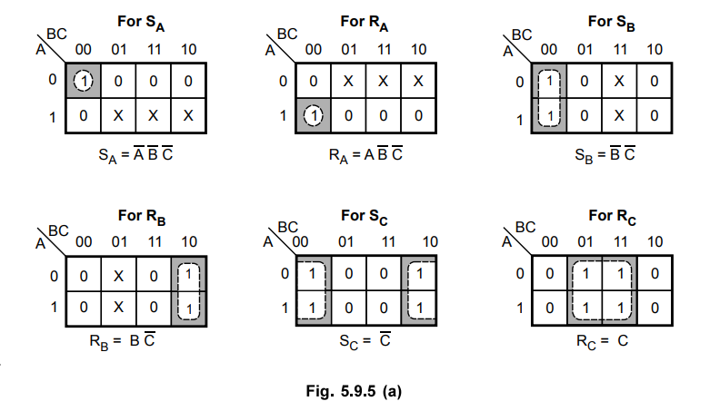
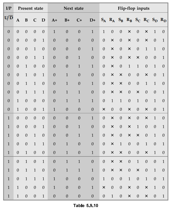
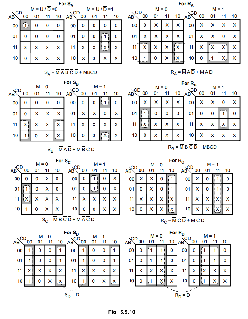
5.9.6 Design a BCD up/down counter using SR flip-flops.
Sol.
:
Step
1
: Number of flip-flops needed = 4
Step
2 :
Flip-flops to be used = SR
Step
3 :
Excitation table for counter
Step
4 :
K-map simplification
Step
5 : Logic
diagram

Ex. 5.9.7 Design a synchronous counter using JK flip-flop to count the following sequence 7, 4, 3, 1, 6, 0, 7
AU
: May-09, Marks 16
Sol.
:
Step
1 :
Since 23 > 7, three flip-flops are required
Step
2 :
Flip-flops to be used : JK
Step
3 :
Excitation table for counter

Ex.
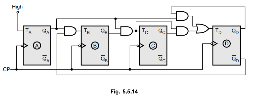
5.9.8 Design and implement a synchronous decade counter using T flip-flop. Draw
the timing diagram.
AU
: May-08, 10, 11, Dec.-15, Marks 16
Sol.
:
Step
1 :
Since N = 10, n = 4 i.e. flip-flops needed = 4
Step
2 :
Flip-flops to be used : T
Step
3 :
Determine excitation table for counter

Step
4 :
K-map simplification
Step
5 :
Logic diagram
Step
6 :
Timing diagram
Fig.
5.9.15 shows the timing diagram for the synchronous decade counter.

Ex.
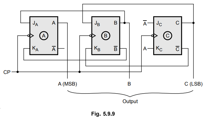
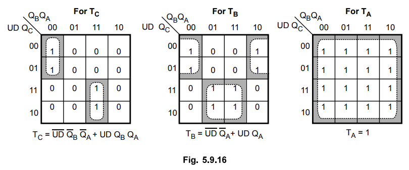
5.9.9 Design a 3-bit synchronous updown counter using T flip-flops.
Sol.
:
Table 5.9.12 shows the excitation table for 3-bit up/down synchronous counter
using T flip-flops.
Excitation
table

K-map
simplification
Logic
diagram

Ex.
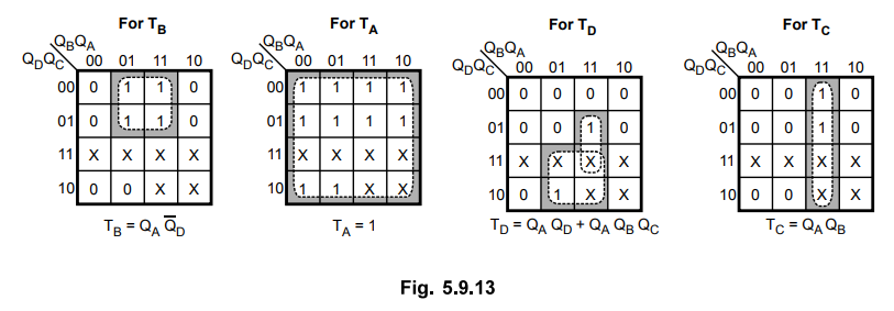
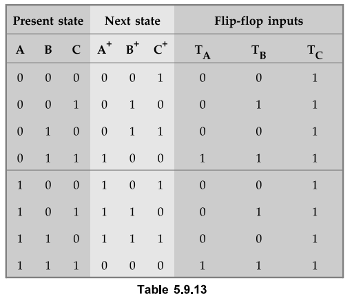
5.9.10 Design a three bit binary counter using T flip-flops.
Sol.
:
Table 5.9.13 shows the excitation table for 3-bit binary counter.
K-map
simplification

Logic diagram

Ex.
5.9.11 Design and explain the working of a synchronous mod-3 counter.
AU
: CSE : May-03, Marks 16
Sol.
:
N = 3 and
Step
1 :
Since 22 > 3, n = 2 i.e. flip-flops needed = 2.
Step
2 :
Flip-Flops used : JK
Step
3 :
Transition table

Step
4 :
K-map simplification
Step
5 : Logic diagram

Ex.
5.9.12 Design and explain the working of mod-7 counter.
Sol.
:
Step
1 : N
= 7, and since 23 > 7, n = 3 i.e. Flip-Flops needed = 3
Step
2 :
Flip-Flops used : JK
Step
3 :
Transition table

Step
4 :
K-map simplification

Step
5 :
Logic diagram
Ex.
5.9.13 Design a synchronous counter with states 0, 1, 2, 3, 0, 1. …… using JK
FFs. AU : CSE : May-04, Marks 16
Sol.
:
Step
1 :
Here, N = 4 and since 22 ≥ 4
we need 2 Flip-Flops
Step
2 :
Flip-Flops to be used : JK
Step
3 :
Transition table
Step
4 :
K-map simplification

Step
5 :
Logic diagram

Ex.
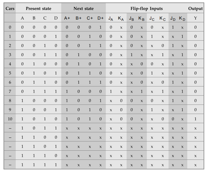
5.9.14 Assume that there is a parking area in a shop whose capacity is 10. No
more than 10 cars are allowed inside the parking area and the gate is closed as
soon as the capacity is reached. There is a gate sensor to detect the entry of
car which is to be synchronized with the block pulse. Design and implement a
suitable counter using JK flip flops. Also, determine the number of flip flops
to be used if the capacity is increased to 50.
Sol.
: State Table
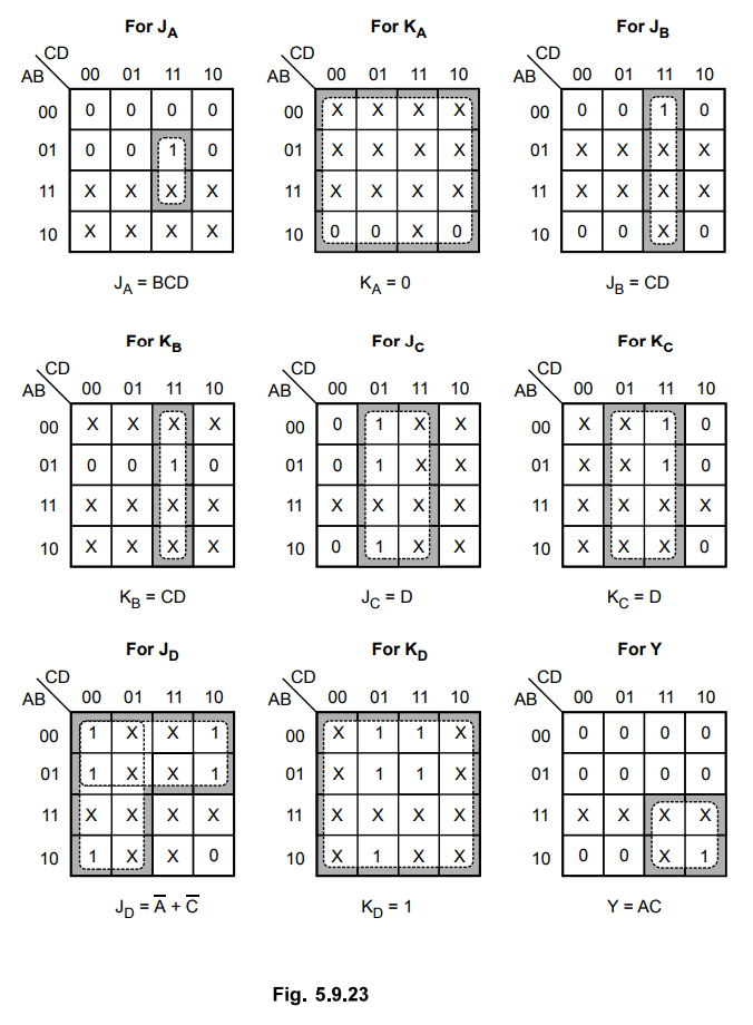
K-map
Simplification
Logic
Diagram

Digital Logic Circuits: Unit III: (b) Analysis & Design of Synchronous Sequential Circuits : Tag: : - Design of Synchronous Counters
Related Topics
Related Subjects

Digital Logic Circuits
EE3302 3rd Semester EEE Dept | 2021 Regulation | 3rd Semester EEE Dept 2021 Regulation