Microprocessors and Microcontrollers: Unit IV: (e) Keyboard and Display Controller - 8279
Display Interfacing
Static LED, Multiplexed
Most of the microprocessor-controlled instruments and machines need to display letters of the alphabet and numbers to give directions or data values to users. This information can be displayed using CRT, LED or LCD displays.
Display Interfacing
AU
: Dec.-04,05, May-06,18
Most
of the microprocessor-controlled instruments and machines need to display
letters of the alphabet and numbers to give directions or data values to users.
This information can be displayed using CRT, LED or LCD displays. CRT displays
are used when a large amount of data is to be displayed. In systems where only
a small amount of data is to be displayed, simple LED and LCD displays are
used.
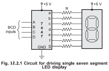
1. Interfacing Static LED Display
Fig.
12.2.1 shows a circuit to drive a single, seven segment, common anode LED
display. For common anode, when anode is connected to positive supply, a low
voltage is applied to a cathode to turn it on. Here, BCD to seven segment
decoder, IC 7447 is used to apply low voltages at cathodes according to BCD
input applied to 7447. To limit the current through LED segments resistors are
connected in series with the segments. This circuit connection is referred to
as a static display because current is being passed through the display at all
times.
The
value of the resistor in series with the segment can be calculated as follows :
We
know, VCC - drop across LED segment - IR = 0
Drop
across LED segment is nearly 1.5 V.
ஃ IR = VCC - 1.5 V = 5 -
1.5 V
=
3.5 V
Each
LED segment requires a current of between 5 and 30 mA to light. Let's assume
that current through LED segment is 15 mA.
ஃ R = 3.5 V / 15 mA = 233 Ω
In
practice, the voltage drop across the LED and the output of 7447 are not
exactly predictable and the exact current through the LED is not critical as
long as we don't exceed its maximum current rating. Therefore, a standard value
220 Ω can be used.
The
static display circuits work well for driving just one or two LED digits.
However, these circuits are not suitable for driving more LED digits, say 8
digits. When there are more number of digits, the first problem is power
consumption. For worst-case calculations, assume that all eight digits with all
segments are lit. Therefore, worst case current required is
1
= 8 (digits) × 7 (segment) × 15 mA (current per segment)
=
840 mA
A
second problem of the static approach is that each display digit requires a
separate BCD to 7 segment decoder.
2. Interfacing Multiplexed Display
To
solve the problems of the static display approach, multiplexed display method
is used. Fig. 12.2.2 shows the 4 seven segment displays connected using
multiplexed method. Here, common anode seven segment LEDs are used.
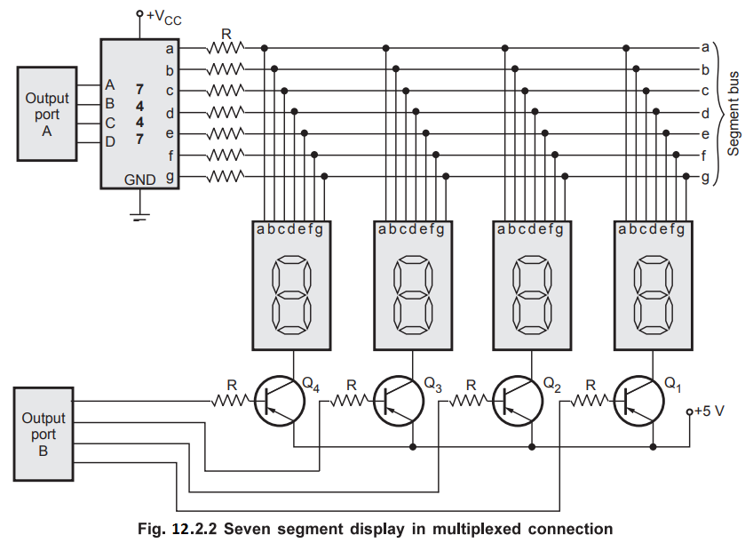
Anodes
are connected to +5 V through transistors. Cathodes of all seven segments are
connected in parallel and then to the output of 7447 IC through resistors.
Looking at the Fig. 12.2.2, the question may occur in our mind
that,"Aren't all of the digits going to display the same number?" The
answer is that they would show the same number only if all the digits are
turned on at the same time. However, in multiplexed display the segment
information is sent for all digits on the common lines (output lines of 7447), but
only one display digit is turned on at a time. The PNP transistors connected in
series with the common anode of each digit act as an ON and OFF switch for that
digit. Here's how the multiplexing process works.
The
BCD code for digit 1 is first output from port A, to the 7447. The 7447, BCD to
seven segment decoder outputs the corresponding seven segment code on the
segment bus lines. The transistor Q 1 connected to digit 1 is then turned on by
outputting a low to that bit of port B. All of the rest of the bits of port B
are made high to ensure no other digits are turned on. After 2 ms, digit 1 is
turned OFF outputting all highs to port B. The BCD code for digit 2 is then
output to the port A, and bit pattern to turn on digit 2 is output on port B.
After 2 ms, digit 2 is turned off and the process is repeated for digit 3 and
digit 4. After completion of turn for each digit, all the digits are lit again
in turn.
With
4 digits and 2 ms per digit we get back to digit 1 every 8 ms or about 125
times a second. This refresh rate is fast enough that, to our eye and due to
persistence of vision all digits will appear to be lit all the time.
In
multiplexed display, the segment current is kept in between 40 mA to 60 mA so
that they will appear as bright as they would if not multiplexed. Even with
this increased segment current, multiplexing gives a large saving in power and
hardware components.
Lab Experiment 12.2.1 : Hardware and
software for interfacing 8-digit 7-segment display.
AU
: May-18
Statement :
Interface an 8-digit 7-segment LED display using 8255 to the 8085
microprocessor system and write an 8085 assembly language routine to display
message on the display.
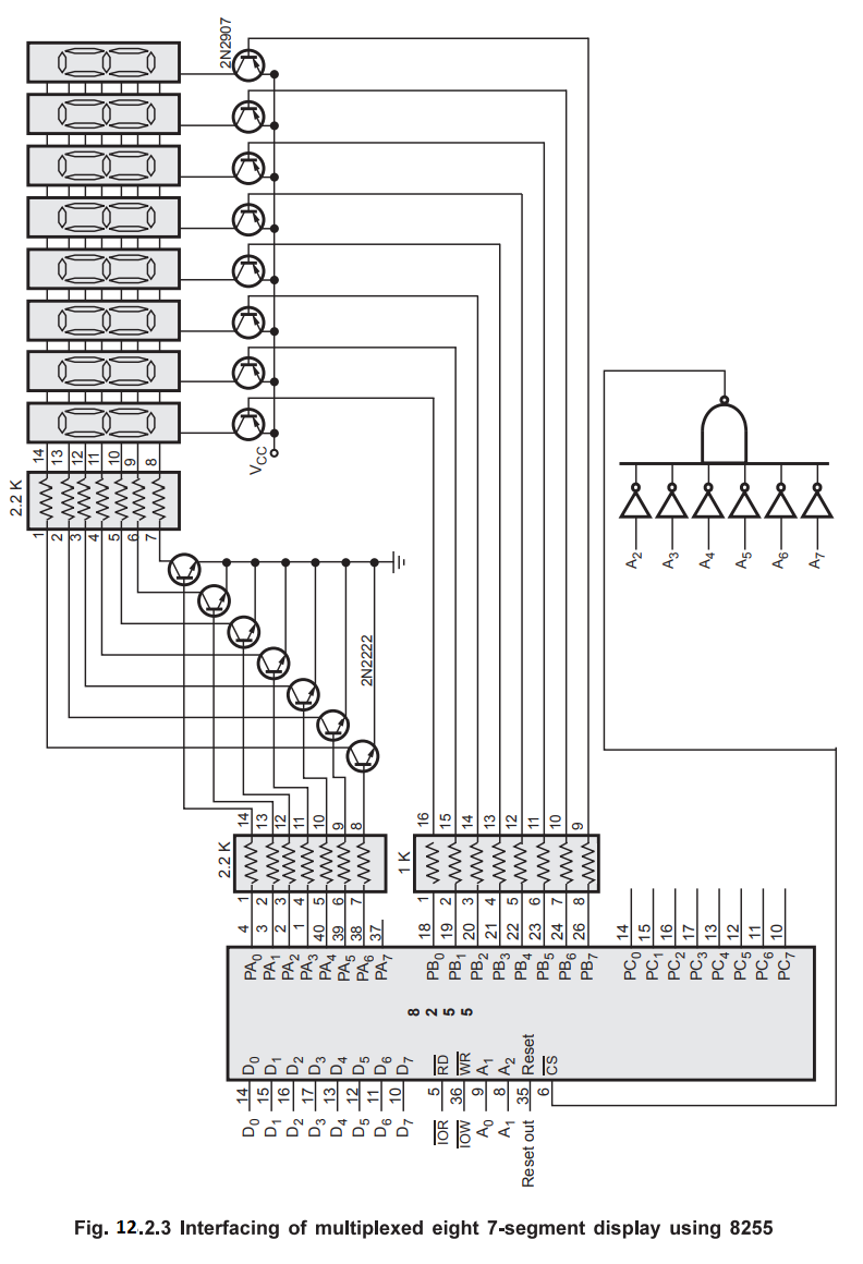
Hardware
: Fig. 12.2.3 shows the multiplexed eight 7-segment display connected in the
8085 system using 8255. In this circuit port A and port B are used as simple
latched output ports. Port A provides the segment data inputs to the display
and port B provides a means of selecting a display position at a time for
multiplexing the displays. A0-A7 lines are used to decode
the addresses for 8255. For this circuit different addresses are :
PA
= 00H PC = 02H
PB
= 01H CR = 03H.
The
register values are chosen in Fig. 12.2.3 such that the segment current is 80
mA. This current is required to produce an average of 10 mA per segment as the
displays are multiplexed. In this type of display system, only one of the eight
display position is 'ON' at any given instant. Only one digit is selected at a
time by giving low signal on the corresponding control line. Maximum anode
current is (7 - segments × 80 mA = 560 mA) but the average anode current is 70
mA.
Software
:
Before going to write the software we must know the control word to program
8255 according to hardware connections. For 8255 Port A and B are used as
output ports.
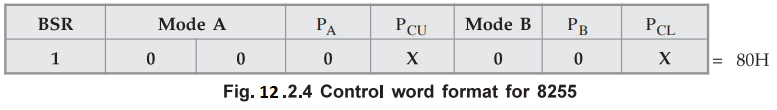
;
Software to initialize 8255
MVI
A, 80H ; Load control word in AL
OUT
CR ; Load control word in CR
;
Subroutine to display message on multiplexed LED display
;
set up registers for display
MVI
B, 08H ; load count
MVI
C, 7FH ; load select pattern
LXI
H, 6000H ; starting address of message
;
display message
DISP_1
: MOV A, C ; select digit
OUT
PB ;
MOV
A, M ; get data
OUT
PA ; display data
CALL
DELAY ; wait for some time
MOV
A, C
RRC
MOV
C, A ; adjust selection pattern
INX
H
DCR
B ; Decrement count
JNZ
DISP_1 ; repeat 8 times
RET
Note
This subroutine must be called continuously to display the 7-segment coded
message stored in the memory from address 6000H.
Disadvantage
of software approach
In
the last example, we have seen the software approach to drive multiplexed
displays. In software approach CPU has to look after digit selection in
synchronism with the data for specific digit. In other words, CPU has to give
digit data on one port and then the digit selection bit pattern on the another
port in synchronism. The process of refreshing has to be repeated all the time,
which puts an additional burden on the CPU. This is a major disadvantage of the
software multiplexing approach. Another disadvantage of software multiplexing
approach is that, if CPU gets involved in going some lengthy task which cannot
be interrupted to refresh the display, only one digit of the display will be
left lit.
An
alternative approach to interface multiplexed displays to microprocessor
systems is to use a dedicated keyboard and display controller 8279, designed by
Intel. IC 8279 independently keeps display refresh and scans the matrix
keyboard. In the next section, we will see the details of 8279 and its
interfacing with 8085 microprocessor.
Review Questions
1. Explain the seven
segment LED interface with microprocessor.
AU : Dec.-04, May-06,
Marks 16
2. Design an interface
circuit needed to connect DIP switch as an input device and display the value of
the key pressed using a 7 segment LED display. Using 8085 system, write a
program to implement the same.
AU : Dec.-05, Marks 16
Microprocessors and Microcontrollers: Unit IV: (e) Keyboard and Display Controller - 8279 : Tag: : Static LED, Multiplexed - Display Interfacing