Electrical Machines II: UNIT I: c. Synchronization and Parallel Operation of Alternators
Effect of Change in Input or Mechanical Torque
Alternator
For any alternator its driving torque can be changed by controlling the gate opening in case of hydrogenerators or by controlling the throttle opening in case of turbogenerators.
Effect of Change in Input or Mechanical Torque AU
: NOV.-04, May-04, 07, 13, Dec.-l0
For
any alternator its driving torque can be changed by controlling the gate
opening in case of hydrogenerators or by controlling the throttle opening in
case of turbogenerators. Again we will consider two cases that are alternator
with and without load respectively.
1. Alternator on No Load
Suppose
that two alternators are running in parallel without any load on them. The
excitations for two alternators are adjusted in such a way that the induced
e.m.f.s. are equal in magnitude. The resultant voltage in the local circuit
will be zero. With respect to external circuit the two e.m.f.s are in phase
whereas in local circuit they are in opposition.
Now
the driving torque of alternator 1 is increased. This increment in torque will
try to accelerate the alternator 1 and its induced e.m.f. E1 will lead e.m.f.
E2. This will give rise to resultant voltage Er. This voltage 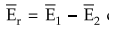 circulates current IgY in local circuit which is given by

This
current lags behind Er by angle of approximately 90° if the
resistances of the armatures of the two alternators are neglected. This is
represented in following phasor diagram shown in Fig. 3.15.1.
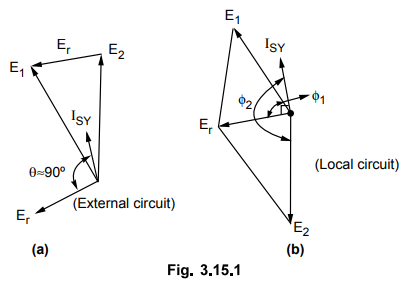
This
circulating current ISY is almost in phase with E1 and in
phase opposition with E2. Now here the synchronizing power will come
into play. The alternator 1 produces a power E1 ISY cos ϕ1
which is positive as ϕ1 < 90° while alternator 2 generates a power E2 ISY
cos ϕ2 which is negative as ϕ2
< 90° Alternately we can say that alternator 1 experiences a
generating action which will try to retard it and alternator 2 receives the
power produced by alternator 1. Hence it will experience a motoring action
which will tend to accelerate it. Thus there will be automatic synchronizing
action which will retard the faster machine and accelerate the slower machine
and synchronism is maintained.
It
can be seen that the autosynchronizing action is on account of Z1
and Z2considered mainly reactive. If Z1 and Z2
are purely resistive then ISY will be in phase of Er. Then power for
both the machines is positive and both will experience generating action. So
there would not be synchronizing power that will tend to accelerate the slower
machine.
Key
Point Thus reactance mainly causes auto
synchronization but it is bad for voltage regulation.
2. Alternator on Load
Again
we will consider two alternators which are loaded and running in parallel. The
sharing of load between these alternators is governed by speed-load characteristics
of their prime movers. In the Fig. 3.15.2 the two alternators are shown driven
by prime movers 1 and 2.

In
Fig. 3.15.3 the lines 1 and 2 represent the speed load characteristics of prime
movers 1 and 2 . For clarity and simplicity the slopes are exaggerated.

Horizontal
line ab represents total load of 2P with load on each alternator as P. The
frequency of bus bar is f.
Now
if by govemer setting, the torque of prime mover 1 is increased, its speed will
be increased which will shift its speed-load curve upwards. This is shown by
dotted line 1'. The original operating points a and b are now shifted to c and
d. This will give new operating conditions which will increase load on alternator 1 from P to P1 and
decrease load on alternator 2 from P to P2 with P1 + P2
= 2P. From the Fig. 3.15.3 it can be seen that frequency has increased from f
to f'. Now, if it is desired to maintain the frequency constant then the input
to prime mover 2 must be reduced which will shift its speed-load curve downward
shown by dotted line 2'. The operating points c and d now shift to new points x
and y. The horizontal line xy indicates that the load on alternator 1 is
further increased from P1 and P1 and 2that on alternator
2 is reduced from P to P2 such that the relation P1 + P2
= 2P is maintained. Thus the load sharing between the alternators and the
frequency can be controlled by changing the mechanical torque input to the
alternators. By controlling the gate opening of water turbines or the throttle
opening of steam turbines, the speed-load characteristics of prime movers can
be shifted up and down.
3. Phasor Diagram
To
consider what happens internally in the two alternators, let us consider the
phasor diagram.
The two alternators are running in parallel with their excitations constant. The armature currents I1 and I2 are also equal so that total load current is 2I1 or 2I2 . The terminal voltage V is constant. Each alternator is sharing a load equal to E1V / Xs sin δ = E2V / Xs sin δ = P.
Now
when mechanical torque of alternator 1 is increased, its output will also
increase. But E1 V and Xs are constant. So to increase
power output power angle must be increased from δ to δ1, so new E1,
will be ahead of previous position. The alternator 1 shares greater load than
P. Therefore for constant load of 2P the load on alternator 2 must be less than
P. This will make new E2 to fall back from its previous position.
Due to the different positions of E1, and E2, resulting
voltage AB appears in the local circuit which will send a circulating current ISY
lagging behind the voltage by 90°. This current ISY must be added to
I1, and subtracted from I2.

The
alternator 1 carries increased current I1 and alternator 2 carries
decreased current I2 but total load current remains same  .
The power factor of alternator 1 is improved from cos ϕ to cos ϕ1 whereas
it is reduced from cos ϕ to cos ϕ2 for alternator 2. But the load
power factor remains unaffected.
.
The power factor of alternator 1 is improved from cos ϕ to cos ϕ1 whereas
it is reduced from cos ϕ to cos ϕ2 for alternator 2. But the load
power factor remains unaffected.
Thus
increase in mechanical torque in case of alternator will increase armature
current and improve the power factor. The alternator will share increased load
whose driving torque is increased whereas the other alternator which is in
parallel is relieved from the load whereas the reactive power distribution
remains unaffected.
To
consider the effect of change in input on corresponding power triangles of the
two alternators we will assume that the two alternators are turbo alternators
whose prime movers are supplied with steam.
Now
the excitations for the two alternators are kept constant where steam supply
i.e. power input to prime mover of alternator 1 is increased. The two
alternators are running in synchronism. So machine 1 cannot overrun machine 2.
The increased power input for alternator 1 makes it possible for carrying more
load. This will make rotor for machine 1 advancing its angular position by an
angle δ .
The
resultant e.m.f. Er is produced in the local circuit which will set
up a circulating current ISY which lags Er by 90° and
almost in phase with E1. The power per phase for alternator 1 is
increased by an amount E1 ISY whereas it is decreased by same amount
for alternator 2. This current ISY has no appreaciable reactive
component and it will not disturb the reactive power distribution but active
power output of alternator 1 will increase and that of 2 will decrease. This is
shown in Fig. 3.15.5.

Key Point : The change in
input to the prime mover will change the distribution of load between the
alternators.
Example
3. 15. 1 A 3 phase, star connected alternator
with R = 0.4 Q/ph and X = 6 Ω/phase delivers 300 Amps at a power factor of 0.8
lag to constant voltage, constant frequency 10 kV bus bar. If the steam supply
is unchanged, find the percentage change in the induced e.m.f. necessary to
raise the power factor to unity. Ignore changes in losses.
Solution
:

Power
developed in alternator = Power delivered to bus bar + I2R losses in
armature

As
rotational losses are assumed constant with steam supply unchanged, the power
developed by alternator remains constant. With p.f. changed to unity, the
armature current can be found as below.
Power
developed in alternator = Power delivered to bus bar + I2R losses in
armature

Example
3.15.2 Two identical 2000 kVA alternators operate in
parallel. The governor of the prime mover of first machine is such that the
frequency drops uniformly from 50 Hz on load to 48 Hz on full load. The
corresponding uniform speed drop of the second machine is 50 Hz to 47.5 Hz.
Find :
i)
How will the two machines share a load of 3000 kW ?
ii)
What is the maximum load of unity p.f. that can be delivered without
overloading either machine ?
Solution
:
The
speed-load characteristics of the two alternators can be drawn as shown in Fig.
3.15.6.

Line
PQ is drawn for machine 1 while line PR is drawn for machine 2. At any load the
frequency of the two machines must be same. A line AB is drawn at a frequency x
measured from point P. Total load at this frequency is given as 3000 kW.
AC
+ CB = 3000
Using
the similarly of the triangles PAC and PQS


Example
3.15.3 Two exactly similar turbo alternators are rated
at 25 MW each. They are running in parallel. The speed-load characteristics of
the driving turbines are such that the frequency of alternator 1 drops
uniformly from 50 Hz on no load to 48 Hz on full load and that of alternator 2
from 50 Hz to 48.5 Hz. How will the two machines share a load of 30 MW ?
Solution
:
Refer
example 3.15.2 for the procedure and verify the answer as 12.85 MW and 17.15
MW.
Example
3.15.4 Two
similar, 3 phase alternators work in parallel and deliver a total real power of
1800 kW at 11 kV and at 0.85 pf lagging to the load. Each alternator initially
supplied half the load power. The excitation of the first alternator is then
increased such that its line current becomes 60 A lagging. Find the line
current delivered by the second alternator. Find the power factor of each
alternator.
Solution
:
The load current is,
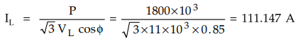
Wattfull
or active component of current = IL cos ϕ = 94.475 A
Wattless
or reactive component of current = IL sin ϕ = 58.55 A
Each
alternator supplies half the load hence, current supplied by each machine = IL
/ 2 = 55.5735 A. Since the steam supply of the first machine is not changed,
the working components of both machines would remain the same as IL
cos ϕ / 2 94.475 / 2 = 47.2375 A.
But
the wattless or reactive component changes due to change in excitation. The
line i.e. armature current of the first machine is changed from 55.5735 A to 60
A.
Wattless
component of 1st machine = √602 - 47.23752 = 36.9948 A
Wattless
component of 2nd machine = 58.55 - 36.9948 = 21.555 A
Armature
current of 2nd machine = √47.23752 + 21.5552 = 51.923 A
The
current diagrams are shown in the Fig. 3.15.7.

Examples
for Practice
Example
3.15.5 Two identical 4000 kVA alternators operate in
parallel. The govemer of the prime mover of first machine is such that the
frequency drops uniformly from 50 Hz on load to 48 Hz on full load. The
corresponding uniform speed drop of the second machine is 50 Hz to 47.5 Hz.
Find.
: i) How will the two machines share a load of 6000 kW ?
ii)
What is the maximum load of unity pf. that can be delivered without overloading
either machine ?
[Ans.:
2667 kW, 3333 kW, 7200 kW]
Example
3.15.6 Two similar 6.6 kV, 3-phase generators are
running in parallel at constant voltage and freuency bus bars. Each has an
equivalent resistance and reactance of 0.05 ohms and 0.5 ohms respectively and
supplies one half of a total load of 10000 kW at a lagging power factor of 0.8,
the two machines being similarly excited, If the excitation of one machine is
adjusted until the armature current is 438 A and the steam supply to the turbine
remains unchanged, find the armature current, the e.m.f. and the power factor
of the other alternator.
[Ans.:
769.21 A, 0.5686,7193.06 V]
Example
3.15.7 Two exactly similar turbo-alternators are rated 20
MW each. They are running in parallel. The speed-load characteristics of the
driving turbines are such that the frequency of alternator 1 drop uniformly
from 50 Hz on no-load to 48 Hz on full-load, and that of alternator 2 from 50
Hz to 48.5 Hz. How will the two machines share a load of 30 MW ? JNTU
: Nov.-04
[Ans.:
12.85 MW, 17.15 MW]
Example
3.15.8 Two 750 kW alterantors operate in parallel. The
speed regulation of one set is 100 % to 102 % from full-load to no-load and
that of the other is 100 % to 104 %. How will the two alternators share a load
of 1000 kW and at what load will one machine fail to supply any portion of the
load ? JNTU : Nov.-04
[Ans.:
420 kW, 580 kW, 375 kW]
Review Question
1. Dissuss the effect of change in the input power on the
alternators running in parallel. AU : May-07, Marks 8
Electrical Machines II: UNIT I: c. Synchronization and Parallel Operation of Alternators : Tag: Engineering Electrical Machines - II : Alternator - Effect of Change in Input or Mechanical Torque
Related Topics
Related Subjects

Electrical Machines II
EE3405 Machine 2 EM 2 4th Semester EEE Dept | 2021 Regulation | 4th Semester EEE Dept 2021 Regulation