Physics for Electrical Engineering: Unit II: a. Electrical Properties of Materials
Electrical Properties of Materials
When an electrical current flows through a conductor, then the voltage drop across the conductor is given by the ohm's law
Unit - II
Electrical
and Magnetic Properties of Materials
2(a)
Electrical Properties of Materials
Classical
free electron theory - Expression for electrical conductivity - Thermal
conductivity expression - Quantum free electron theory :Tunneling - degenerate
states Ferm i- Dirac statistics - Density of energy states Electron in periodic
potential - Energy bands in solids - tight binding approximation - Electron
effective mass concept of hole
Introduction
It
is essential to study the various electrical properties of the solids for their
specific applications.
In
terms of electrical properties, all solid state materials are classified into
three groups as conductors, semiconductors and dielectrics or insulators.
The
selection of materials for different applications depends on their electrical
properties as well as requirements of the job.
Electrical
phenomena are caused by the motion of electrons in solids and find many
applications in day-to-day activities.
Electrons
in a metallic filament and the property of electrical resisivity of the
material are used in incandescent lamps for heating and illumination in a
variety of domestic and dustrial applications.
In
recent times, the mobility of electrons is being exploited in solar cells,
lasers, in the control of thermonuclear reactions and many other applications.
The
chapter mainly deals with the electrical conduction, thermal conduction,
density of states, number of electrons per unit volume in a metal etc.
Besides,
it also deals with the classical, quantum free electron theories and band
theory to explain the conductivity of the solid state materials.
Basic definition
It
is necessary to know the basic relations in electrical conductivity to
understand its derivation.
Ohm's Law
When
an electrical current flows through a conductor, then the voltage drop across
the conductor is given by the ohm's law
V=IR
(or) I= V / R...(1)
where
I - current in ampere,
R
- resistance to the current flow in ohm
V
- voltage drop across the conductor in volt.
Resistance (R)
The
resistance R of a conductor is a geometry (length and area) and property
dependent factor of the material used.
R
∝ l / A
R
= ρ l / A = l / σ A ...(2)
Ρ
- Proportionality constant known as resistivity (ohm m) ρ = 1/ σ
1-
Length of the conductor (m)
A-
Area of cross section (m2)
σ-
Electrical conductivity (ohm-1m-1) (or) (mho m-1)
(or) siemens m-1 (Sm-1)
Current Density (J)
It is defined as the current per
unit area of cross section of a current carrying conductor.
If I is the current and A is the area of cross-section, then current density is
given by
J
= I / A ....(3)
Its
unit is Am-2
Electrical Field (E)
The
electrical field E in a conductor of uniform cross section is defined as the
potential drop (voltage) V per unit length.
E
= V / l ...(4)
Its
unit is Vm-1
Electrical Conductivity (σ)
The amount of electrical charges
(Q) conducted per unit time across unit area (A) of a conductor per unit
applied electrical field (E) is defined as electrical conductivity.
It
is denoted by o and it is given by
σ
= Q / tAE
σ
= Q / tAE = J / E
where
J is the current density and it is given by ( Q / tA )
A
second form of ohm's law is obtained by combining equations (1) and (2)
From
eqn (1), V=IR
From
eqn (2), R= l / σA
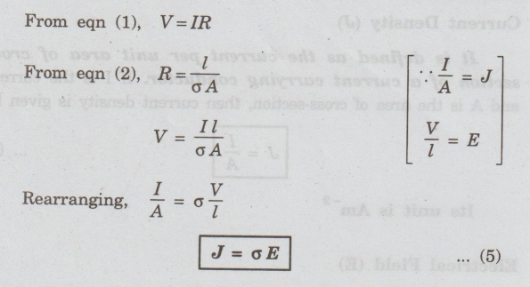
Rearranging,
I / A = σ V / l
J
= σ E ...(5)
Relation between Current Density J, Drift Velocity Vd and Mobility μ
Let n be the number of charge carriers per
unit volume (also called charge carrier density) in a conductor of length with
uniform cross sectional area A. The current flow through the conductor is given
by
I
= Total charge / Time = Q/ t
=
ne Al / t = ne Avd ...(6)
where
vd = l / t is called the drift velocity. It is the average velocity
gained by the charge carriers in the presence of an electrical field.
But,
we know that J = I / A
Using
the eqn (6), J is written as
J
= ne Avd / Avd = ne vd
J = nevd ....(7)
But
J= σ E.
Therefore,
the eqn (7) becomes
σ E = nevd
σ
= ne vd / E
Hence
, σ = neμ ...(8)
gnibyo00A
8ser radi ni dold vd Benog
where
μ = vd / E is called the
mobility of the charge carrier. It is defined as the drift velocity per unit
electric field. Its unit is m2 V-1 s-1.
Free Electron theory of solids
It
is well known that the electrons in the outermost orbit of the atom determine
the electrical properties of a solid. The
free electron theory of solids explains the structure and properties of solids
through their electronic structures.
This
theory is applicable to all solids, both metals and non-metals. It explains
•
The behaviour of conductors, semiconductors and insulators.
•
The electrical, thermal and magnetic properties of solids.
Main Stages of Free Electron theory
of solids
(i) Classical free electron theory (Drude
and Lorentz free electron theory)
This
theory was proposed by Drude and Lorentz in the year 1900. According to this
theory, the free electrons are mainly responsible for electrical conduction in
a metal.
It
obeys the laws of classical mechanics. Here, the free electrons are assumed to
move in a constant potential.
(ii) Quantum free electron theory (Sommerfeld
Quantum theory)
Quantum
free electron theory was proposed by Sommerfeld in the year 1928. According to
this theory, the electrons in a metal move in a constant potential.
It
obeys the laws of quantum mechanics. The wave nature of electron is taken into
account to describe the electron.
(iii) Zone theory or band theory of
solids
This
theory was proposed by Bloch in the year 1928. According to this theory, free
electrons move in a periodic potential.
It
explains electrical conductivity based on the energy bands.
Physics for Electrical Engineering: Unit II: a. Electrical Properties of Materials : Tag: : - Electrical Properties of Materials
Related Topics
Related Subjects

Physics for Electrical Engineering
PH3202 2nd Semester 2021 Regulation | 2nd Semester EEE Dept 2021 Regulation