Digital Logic Circuits: Unit II: Combinational Circuits
Encoder
Block and Logic diagram, Logic symbol, Function table
• An encoder is a digital circuit that performs the inverse operation of a decoder. An encoder has 2n (or fewer) input lines and n output lines. In encoder the output lines generate the binary code corresponding to the input value.
Encoder
•
An encoder is a digital circuit that performs the inverse operation of a
decoder. An encoder has 2n (or fewer) input lines and n output lines. In
encoder the output lines generate the binary code corresponding to the input
value. The Fig. 3.20.1 shows the general structure of the encoder circuit. As
shown in the Fig. 3.20.1 the decoded information is presented as 2n inputs
producing n possible

1. Decimal to BCD Encoder
•
The decimal to BCD encoder, usually has ten input lines and four output lines.
The decoded decimal data acts as an input for encoder and encoded BCD output is
available on the four output lines.
•
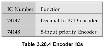
The Fig. 3.20.2 shows the logic symbol for decimal to BCD encoder IC, IC
74XX147. It has nine input lines and four output lines. Both input and output
lines are asserted active low. It is important to note that there is no input
line for decimal zero. When this condition occurs, all output lines are 1. The
function table for the 74XX147 is shown in Table 3.20.1.

2. Priority Encoder
•
A priority encoder is an encoder circuit that includes the priority function.
In priority encoder, if two or more inputs are equal to 1 at the same time, the
input having the highest priority will take precedence.
•
Table 3.20.2 shows truth table of 4-bit priority encoder.

• Table 3.20.2 shows Dg input with highest priority and DQ input with lowest priority. When D3 input is high, regardless of other inputs output is 11. The D2 has the next priority. Thus, when D3 = 0 and D2 = 1, regardless of other two lower priority input, output is 10. The output for D1 is generated only if higher priority inputs are 0, and so on. The output V (a valid output indicator) indicates, one or more of the inputs are equal to 1. If all inputs are 0, V is equal to 0, and the other two outputs (Yj and YQ) of the circuit are not used.
K-map
simplification

Logic
diagram

3. Octal to Binary Encoder
•
Fig. 3.20.5 shows octal to binary encoder. It has eight inputs, one for each
octal digit, and three outputs that generate the corresponding binary code. In
encoders it is assumed that only one input has a value of 1 at any given time;
otherwise the circuit is meaningless.

•
Table 3.20.3 shows the truth table of octal to binary converter.
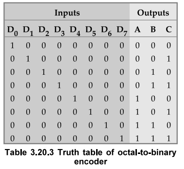
• The above circuit has one more ambiguity that when all inputs are Os the outputs are 0s. The zero output can also be generated when D0 = 1. This ambiguity can be resolved by providing an additional output that specifies the valid condition.
4. Encoder ICs
Review Questions
1. Define encoder.
2. Write a note on encoders.
3. Explain decimal to BCD encoder with logic symbol and truth
table.
4. Define priority encoder.
5. Explain the octal to binary encoder.
Digital Logic Circuits: Unit II: Combinational Circuits : Tag: : Block and Logic diagram, Logic symbol, Function table - Encoder
Related Topics
Related Subjects

Digital Logic Circuits
EE3302 3rd Semester EEE Dept | 2021 Regulation | 3rd Semester EEE Dept 2021 Regulation