Digital Logic Circuits: Unit IV: (a) Asynchronous Sequential Circuits
Examples Problems for Understanding
Asynchronous Sequential Circuits
Digital Logic Circuits: Unit IV: (a) Asynchronous Sequential Circuits : Examples for Understanding
Examples for Understanding
Ex. 7.6.4 Design an asynchronous sequential circuit with two inputs X and Y and with one output Z. Whenever Y is 1, input X is transferred to Z. When Y is 0, the output does not change for any change in X.
Sol. :
Step 1 : Draw state diagram and derive primitive flow table.
The state diagram for above problem statement can be given as shown in Fig. 7.6.12.

A primitive flow table is constructed from the state diagram shown in Fig. 7.6.13.

Step 2 : Reduction of primitive flow table.

Above primitive flow table can be reduced using merger graph as shown in Fig. 7.6.14. Here, six vertices are drawn corresponding to six states, and complete line between states vertices is drawn for compatible states. The merger graph shown in Fig. 7.6.14 gives the two compatible pairs as a set of maximal compatibles
(A, B, C) → S0
(D, E, F) → S1
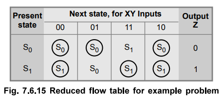
This set of maximal compatibles covers all of the original states resulting in reduced flow table as shown in Fig. 7.6.15.
Step 3 : State assignment
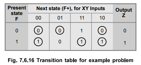
In order to obtain the circuit described by the reduced flow table, it is necessary to assign a distinct binary value to each state. This assignment converts the flow table into a transition table. This state assignment should ensure that the circuit will be free of critical races. In this reduced flow table we have only two rows and fortunately, there cannot be critical races when row in the flow table are two. Therefore, we can assign 0 to state S0 and 1 to state S1 to get transition table as shown in Fig. 7.6.16.
Step 4 : Realization of circuit using logic elements
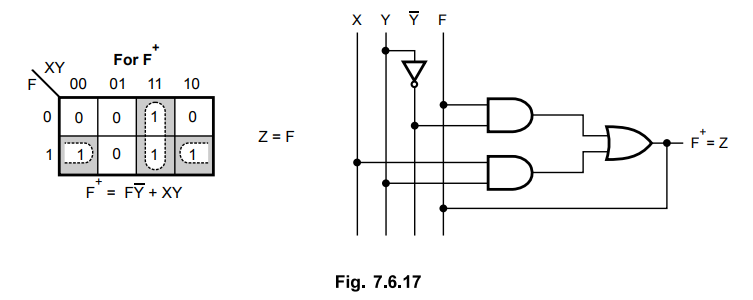
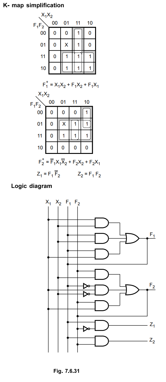
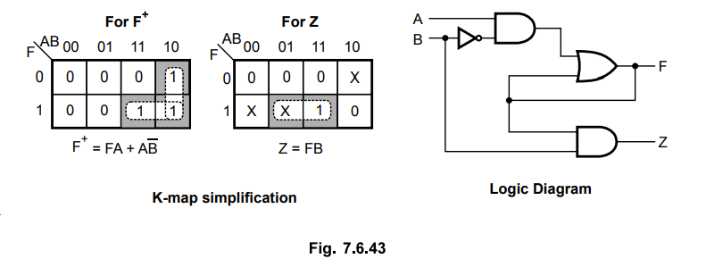
The Boolean expressions for function and the output are derived using K-map simplification. Then each boolean expression is implemented using logic gates, as shown below.
K-map simplification
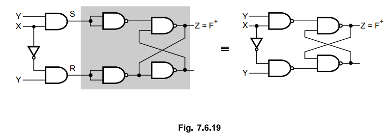
Step 5 : Realization of circuit using SR latch.
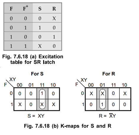
We can also implement the circuit represented by transition table using SR latch. In this case we have to derive the input expressions for S and R inputs of SR latch. To derive the input expressions first we have to obtain the K-map for S and R by referring the excitation table of SR latch and then solve the K-map for S and R, individually. This is illustrated in Fig. 7.6.18. Here, we have to see the transition from transition table and obtain the SR inputs for the transition by referring excitation table of SR latch. For example, for input XY = 01, the second row of transition table shown in Fig. 7.6.18 requires a transition from F = 1 to F+ = 0. The excitation table specifies S = 0, R = 1 for this change. Therefore, the corresponding square in the S map is marked with a 0 and the one in the R map with a 1. All other squares are filled with values in a similar manner.
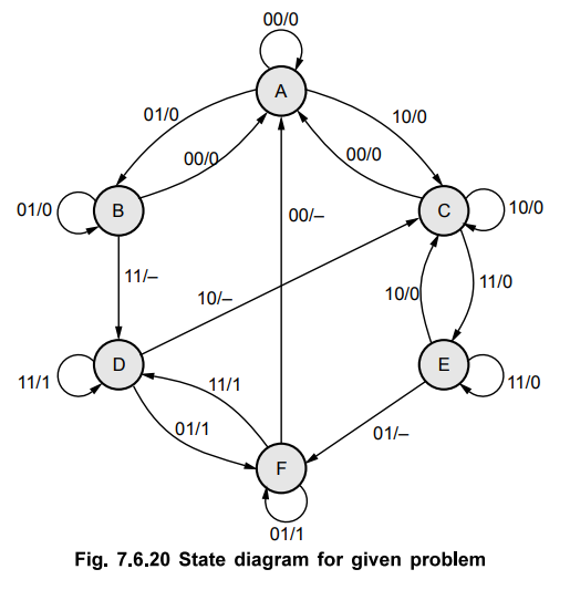
Ex. 7.6.5 Design an asynchronous sequential circuit that has two inputs X2 and X1 and one output Z. When X1 = 0, the output Z is 0. The first change in X2 that occurs while X is 1 will cause output Z to be 1. The output Z will remain 1 until X1 returns to 0.
AU: Dec.-08, May-15, June-09, Marks 16
Solution :
Step 1 : Draw state diagram and derive primitive flow table.
The state diagram for above problem statement can be given as shown in Fig. 7.6.20.
A primitive flow table is constructed from the state diagram shown in Fig. 7.6.21.
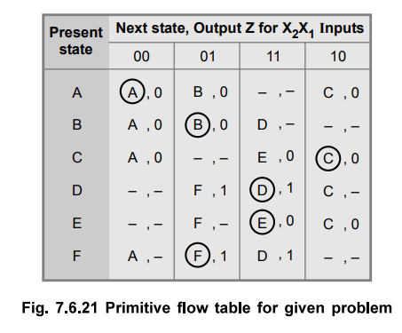
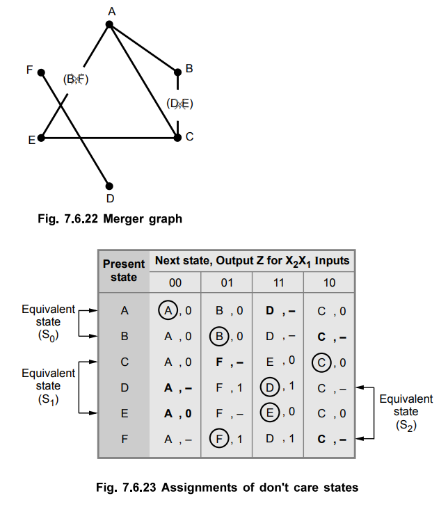
The merger graph for above primitive flow table can be given as in Fig. 7.6.22.
Step 2 : Reduction of primitive flow table
The merger graph gives the two compatible pairs as a set of maximal compatibles.
(A, B) → S0
(C, E) → S1
(D, F) → S2
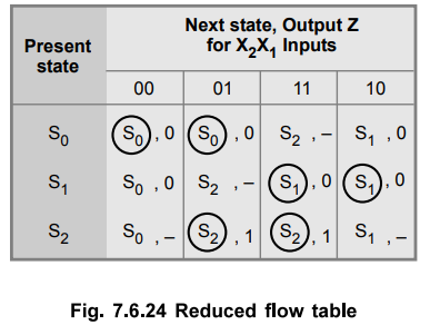
This set of maximal compatible covers all of the original states resulting in the reduced flow table as shown in Fig. 7.6.24.
Step 3 : State assignment
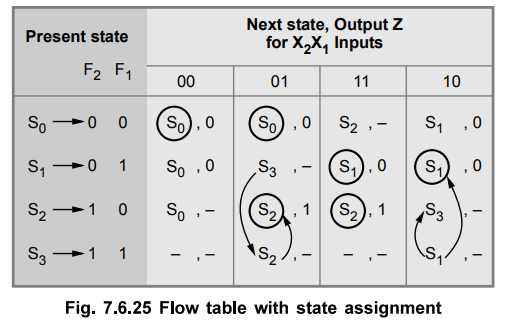
Now if we assign S0 → 00, S1 → 01 and S2 → 10 then we need one more state S3 → 11 to prevent critical race during transition of S1 → S2 or S2 → S1 By introducing S3 the transitions S1 → S2 and S2 → S1 are routed through S3. Thus, after state assignment the flow table can be given as shown in Fig. 7.6.25.
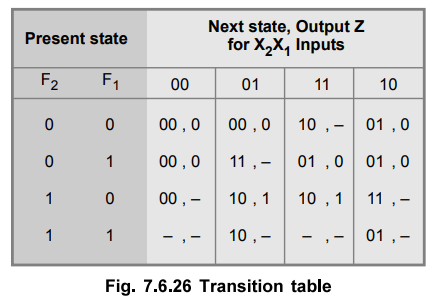
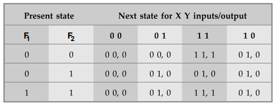
The flow table in Fig. 7.6.25 can be converted to a transition table as shown in Fig. 7.6.26.
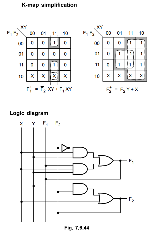
Step 4 : Realization of circuit using logic elements

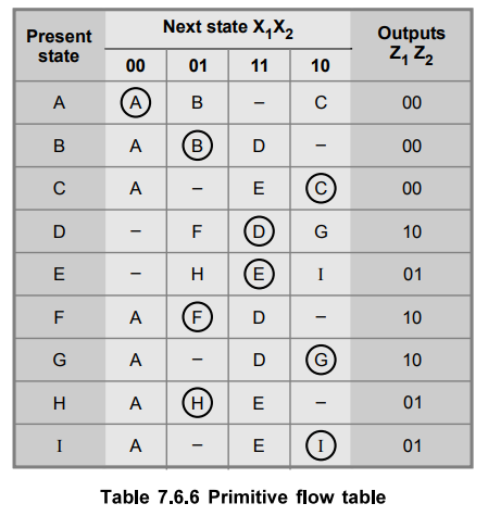
Ex. 7.6.6 Design a two-input (x1,x2), two-output (z1,z2) fundamental-mode circuit that has the following specifications. When x1,x2= 00, z1,z2= 00. The output 10 will be produced following the occurrence of the input sequence 00-01-11. The output will remain at 10 until the input returns to 00 at which time it becomes 00. An output of 01 will be produced following the receipt of the input sequence 00-10-11. And once again, the output will remain at 01 until a 00 input occurs, which returns the output to 00.
Sol. :
Step 1 : Draw state diagram and derive primitive flow table.
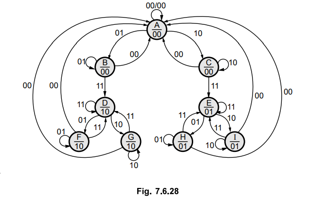
The state diagram for the given problem is as shown in the Fig. 7.6.28.
The Table 7.6.6 shows the primitive flow table constructed from the state diagram.
Step 2 : Reduce primitive flow table.
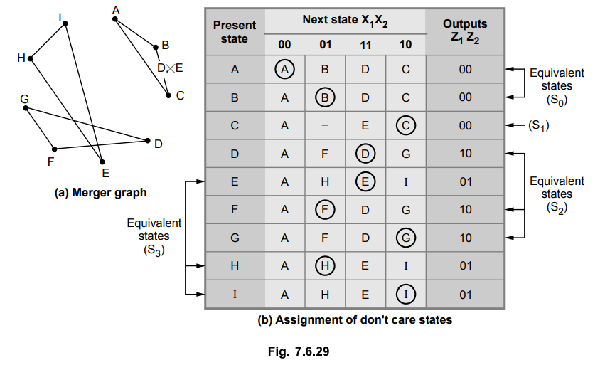
The merger graph gives four compatible pair as a set of maximum compatibilities.
(A, B) → S0
(C) → S1
(D, F, G) → S2
(E, H, I) → S3
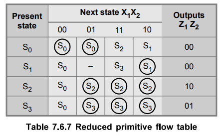
The Table 7.6.7 shows the reduced primitive flow table.
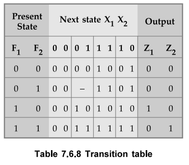
Step 3 : State assignment
We assign : S0 = 00, S1 = 01, S2 = 10 and S3 = 11
The Table 7.6.8 shows the transition table with state assignment.
Step 4: Realization of circuit using logic elements.
Examples with Solutions
Ex. 7.6.7 Obtain a primitive flow table for a circuit with two inputs and x2 and two outputs z2 and z2 that satisfies the following four conditions.
i) When x1x2 = 00 output z1z2 = 00.
ii) When x1 = 1 and x2 changes from 0 to 1, the output z1z2 = 01.
iii) When x2 = 1 and x1 changes from 0 to 1, the output z1z2 = 10.
iv) Otherwise the output does not change.
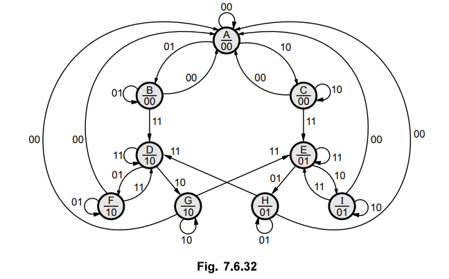
Sol. : The state diagram for above problem statement can be given as shown in Fig. 7.6.32.
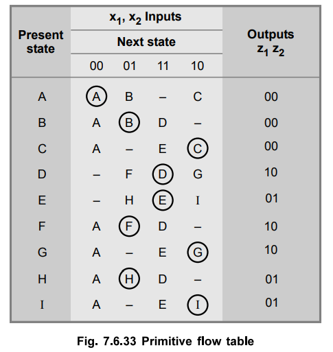
A primitive flow table is constructed from the state diagram shown in Fig. 7.6.33.
Ex.
7.6.8 Design a T flip-flop from logic gates.
Sol.
:
The T flip-flop has one excitation input and one clock input. But here we use
another input P that will function as a clock. The flip-flop will change state
if T = 1 and when the clock (P) changes from 1 to 0. Under all other input
conditions, output Q will remain constant. We assume that T and P do not change
simultaneously.
Step
1:
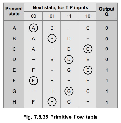
Draw step diagram and derive primitive flow table.
The
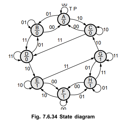
state diagram for above problem state is as shown in Fig. 7.6.34.
Step
2:
Reduction of primitive flow table.
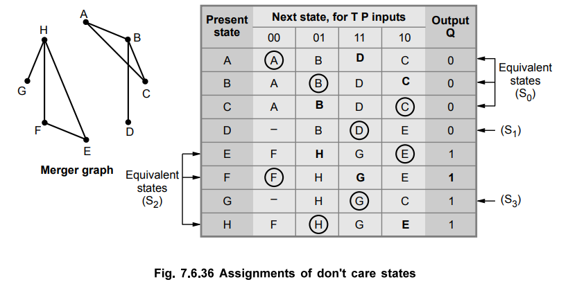
The
merger graph shown in Fig. 7.6.36 gives the four compatible pairs as a set of
maximal compatibles.
(A,
B, C) → S0
(E,
F, H) → S2
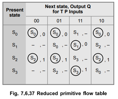
This
set of maximum compatibles covers all of the original states resulting in the
reduced flow table as shown in the Fig. 7.6.37.
Step
3 :
State assignment
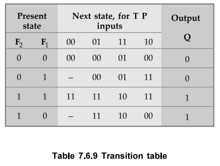
By
making state assignment as S0 → 00, S1 → 01, S2
→11 and S3 →10 we can avoid all the races.
Substituting
state assigned values to state we get transition table as shown in Table 7.6.9.
Step
4 :
Realization of circuit using logic elements

Ex.
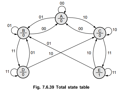
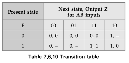
7.6.9 Design a circuit with inputs A and B to give an output Z = 1 when AB = 11
but only if A becomes 1 before B, by drawing total state diagram, primitive
flow table and output map in which transient state is included.
AU
: May-06, Dec.-15
Sol.
:
Step
1 :
Draw state diagram and derive primitive flow table.
The
state diagram for above problem statement can be given as shown in the Fig.
7.6.39.
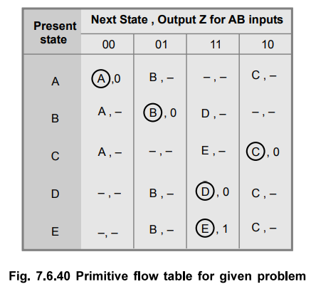
A
primitive flow table is constructed from the state diagram as shown in the Fig.
7.6.40.
Step
2 :
Reduction to primitive flow table.
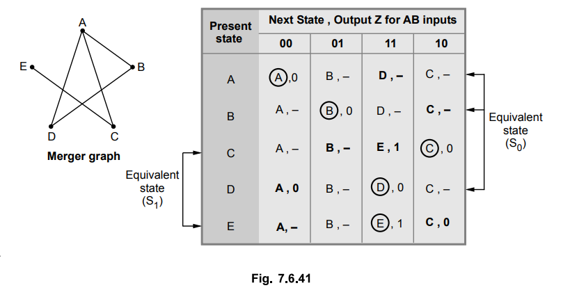
The
merger graph gives two compatible pairs as a set of maximum compatibilities.
(A,B,D)
→ S0 (C, E) → S1
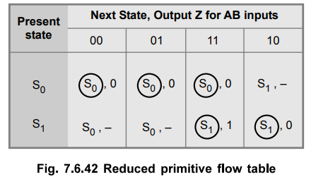
Step
3 :
State assignment
We assign S0 = 0 and S1 = 1
Step
4 :
Realization of circuit using logic elements.
Ex.
7.6.10 Design an asynchronous circuit that has two inputs xl and x2 and one
output z. The circuit is required to give an output whenever the input sequence
(0, 0), (0, 1) and (1, 1) received but only in that order.
Sol.
:
Step
1 :
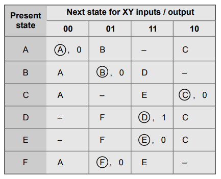
Draw primitive flow table.
Primitive
flow table for given problem is as shown below :
Step
2 :
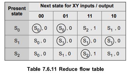
Reduce primitive flow table
States
A and B and states C, E and F are equivalent. Thus we have,
(A,
B) → S0, (C, E, F) → S1
and D → S2
Note
:
In the above Table, 7.6.11 entry in the last row is assigned  0 i.e.
the initial state with output zero.
0 i.e.
the initial state with output zero.
Step
3 :
State assignment
We
assign : S0 =00, S1 = 01 and S2 = 11 and we
get
Step
4 :
Realization of circuit using logic elements
Examples
for Practice
Ex.
7.6.11 Derive the primitive flow table for a positive edge triggered clocked T
flip-flop. The circuit has two inputs, clock and T and one output Q.
[Ans.:
Hint:
Similar to example 7.6.8]
Ex.
7.6.12 Draw and explain the state transition diagram of modulo-6 counter in
asynchronous sequential logic.
AU
: Dec.-11, Marks 12
Ex.
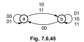
7.6.13 Design an asynchronous sequential logic circuit for the state transition
diagram shown in Fig. 7.6.45.
AU
: Dec.-11, Marks 12
Review Questions
1. Describe the steps involved in design of asynchronous
sequential circuit in detail with an example.
2. Define asynchronous sequential circuit, cycles, critical
race, non-critical race.
3. When do you get the critical and non-critical races ? How
will you obtain race free conditions ?
AU : Dec.-lO, Marks 10
4. Describe with reasons, the effect of races in asynchronous
sequential circuit design. Explain its types with illustrations. Show the
method of race-free state assignments with examples.
AU : Dec.-14, Marks 16
5. Explain cycles and races in asynchronous sequential circuits. CJHEBiiSiHiaJ
6. What are transition table and flow table ? Give suitable
examples.
Digital Logic Circuits: Unit IV: (a) Asynchronous Sequential Circuits : Tag: : Asynchronous Sequential Circuits - Examples Problems for Understanding
Related Topics
Related Subjects

Digital Logic Circuits
EE3302 3rd Semester EEE Dept | 2021 Regulation | 3rd Semester EEE Dept 2021 Regulation