Transmission and Distribution: Unit V: (a) Distribution Systems
FACTS Devices
Static Shychronous Compensator (STATCOM) - Static VAR Compensator (SVC) - Thyristor Controlled Series Capacitor (TSCS) - Unified Power Flow Controller (UPFC)
Questions : 1. List out the various FACTS devices and explain few of them. 2. Draw simple model of UPFC and explain. 3. Write a short note on SVC. 4. Write a short note on TSCS. 5. Compare STATCOM and SVC.
FACTS Devices
AU: May-07, 10, 16, Marks 16
In this section, various FACTS based
devices are listed. The various FACTS devices are as given below.
1. Static Synchronous Compensator
(STATCOM)
2. Static Synchronous Generator (SSG)
3. Static VAR Compensator (SVC)
4. Thyristorized switched or controlled
reactor (TSR/TCR)
5. Thyristor switched capacitor
6. Static VAR Generator or absorber
(SVG)
7. Static VAR System (SVS)
8. Thyristor Controlled Braking Resistor
(TCBR)
9. Static Synchronous Series Compensator
(SSSC)
10. Interline Power Flow Controller
(IPFC)
11. Thyristor Controlled or switched
series capacitor or series reactor (TCSC/TSSC/TCSR/TSSR)
12. Unified Power Flow Controller (UPFC)
13. Thyristor Controlled Phase Shifting
Transformer (TCPST)
14. Interphase Power Controller (IPC)
15. Thyristor Controlled Voltage Limiter
(TCVL)
16. Thyristor Controlled Voltage
Regulator (TCVR)
1. Static Shychronous Compensator (STATCOM)
It is shunt connected static VAR
compensator whose capacitive or inductive output current can be controlled
independently of the ac system voltage. It is shown in the Fig. 7.29.1.
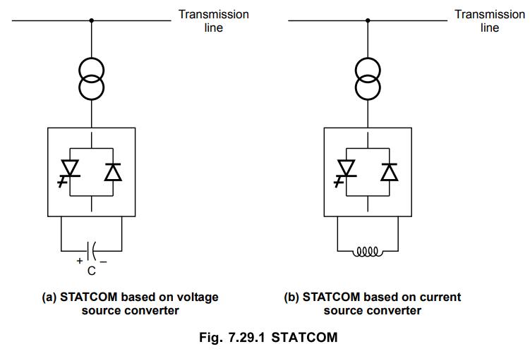
In case of voltage source converter, the
ac output voltage is controlled in such a way as the proper reactive current
will flow for any bus voltage. The dc capacitor voltage is automatically
adjusted as per the requirement so that it acts as voltage source for the
converter. The harmonics in the system can be absorbed by designing STATCOM as
an active filter.
It is a three phase inverter driven by
voltage across capacitor and the three phase output voltages are in phase with
ac system voltages. The difference in the amplitudes of the voltages gives how
much current flows. The reactive power and its polarity can be changed by
controlling the voltage. The performance of STATCOM is better than SVC.
With depression in voltage, STATCOM will
still supply high reactive power by using its over current capability. The
large capacitor present acts as storage device and can continue to deliver some
energy for short duration just like synchronous condenser.
The use of STATCOM needs Gate Turn Off
(GTO) thyristors which are costly as compared to normal thyristors.
2. Static VAR Compensator (SVC)
In STATCOM, converters are used while in
SVC thyristors without gate turn off capability are used. It is shunt connected
static VAR generator or absorber. The output of SVC is adjusted to control
capacitive or inductive current in order to control or maintain certain
parameters, normally magnitude of bus voltage of the power systems. A basic
model of SVC is shown in the Fig. 7.29.2.

The separate equipments are present in
SVC for lagging and leading VARs. It is a low cost substitute for STATCOM. In
STATCOM, the most reactive power that is delivered is product of voltage and
current whereas in case of SVC, it is the square of voltage divided by the
impedance. The reactive power capability steeply falls off as a function of
square of voltage in this case.
a. Comparison of STATCOM and SVC
The Comparison between SVC and STATCOM
is given in this section.

3. Thyristor Controlled Series Capacitor (TSCS)
It is a capacitive reactance type of
compensator consisting of a series capacitor bank connected in parallel with a
thyristor controlled reactor so as to provide smooth variable capacitive
reactance.
It is important type of FACTS controller
based on thyristors without the gate turn off capability. It is shown in the
Fig. 7.29.3.

The Thyristor Controlled Reactor (TCR)
is connected across a series capacitor. When the firing angle of TCR is 180°,
the reactor is nonconducting and the series capacitor has its normal impedance.
If the firing angle is decreased from 180°, the capacitive impedance increases.
The reactor is fully conducting when the firing angle is 90°. In this case, the
total impedance is inductive as the designed value of reactor impedance is less
than the impedance of series capacitor. The TCSC helps in limiting fault
current for a firing angle of 90°.
For geting best performance from TCSC,
it has different sized smaller capacitors or several equal capacitors instead
of a single large unit.
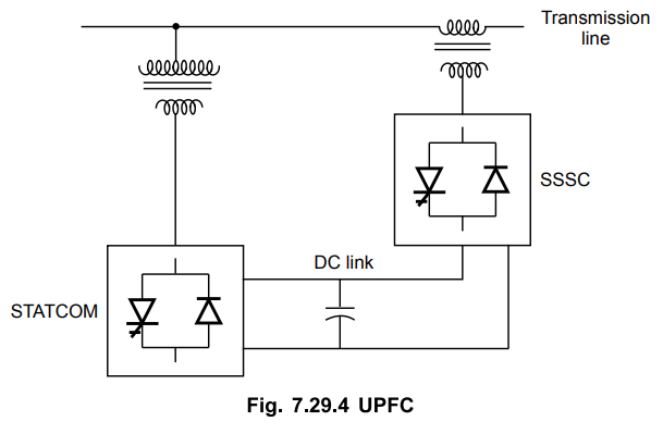
4. Unified Power Flow Controller (UPFC)
It is a combination of Static
Synchronous Compensator (STATCOM) and Static Synchronous Series Compensator
(SSSC). These two are coupled through a dc link and allows bidirectional flow
of real power between series output terminals of SSSC and shunt output
terminals of the STATCOM. These can be controlled to provide real and reactive
series line compensation without an external electrical energy source. It is
shown in the Fig. 7.29.4.
The meaning of UPFC is angular,
unconstrained injection of series voltage to control selectively the line
voltage, impedance and angle. Alternatively, real and reactive power flow in
the line is controlled. The independent controllable shunt compensation is also
provided by UPFC.
UPFC can be made more effective by
connecting additional stroage shunt as a super conducting magnet connected to
the dc link through the electronic interface. The controlled exchange of real
power is possible in case of UPFC.
Review Questions
1. List out the various FACTS devices and explain few of
them.
2. Draw simple model of UPFC and explain.
3. Write a short note on SVC.
4. Write a short note on TSCS.
5. Compare STATCOM and SVC.
Transmission and Distribution: Unit V: (a) Distribution Systems : Tag: : Static Shychronous Compensator (STATCOM) - Static VAR Compensator (SVC) - Thyristor Controlled Series Capacitor (TSCS) - Unified Power Flow Controller (UPFC) - FACTS Devices
Related Topics
Related Subjects

Transmission and Distribution
EE3401 TD 4th Semester EEE Dept | 2021 Regulation | 4th Semester EEE Dept 2021 Regulation