Electromagnetic Theory: Unit IV: Time Varying Fields and Maxwells Equations
Faraday’s Law and Lenz’s Law
• In year 1820, Prof. Hans Christian Oersted demonstrated that a compass needle deflected due to an electric current. After ten years, Michael Faraday, a British Scientist, proved that a magnetic field could produce a current.
Faraday’s Law and Lenz’s Law
AU
: May-95, 04, 06, 07, 09, 14, 17, 18, 19, H Dec.-97, 03, 04, 06, 08, 14, 15,
16, 19
•
In year 1820, Prof. Hans Christian Oersted demonstrated that a compass needle
deflected due to an electric current. After ten years, Michael Faraday, a
British Scientist, proved that a magnetic field could produce a current.
•
According to Faraday's experiment, a static magnetic field can not produce any
current flow. But with a time varying field, an electromotive force (e.m.f.)
induces which may drive a current in a closed path or circuit. This e.m.f. is
nothing but a voltage that induces from changing magnetic fields or motion of
the conductors in a magnetic field. Faraday discovered that the induced e.m.f.
is equal to the time rate of change of magnetic flux linking with the closed
circuit.
Statement
of Faraday's Law : "The electromotive force (e.m.f.)
induced in a closed path (or circuit) is proportional to rate of change of
magnetic flux enclosed by the closed path (or linked with the circuit)."
The statement of Faraday's law was based on the experiments performed by
Faraday and the experiments are commonly known as Faraday's experiment. He
observed that when a closed path moves in a magnetic field, current is
generated and hence e.m.f. The same observations he made with closed path kept
fixed and the magnetic field was varied. The effect is commonly called electromagnetic
induction.
Faraday's
law can be stated as,
e
= -N d ϕ
/ dt volts
where N = Number of turns in the circuit,
e
= Induced e.m.f.
Let
us assume single turn circuit i.e. N = 1, then Faraday's law can be stated as,
e
= - d ϕ
/ dt volts ... (9.2.2)
•
The minus sign in equations (9.2.1) and (9.2.2) indicates that the direction of
the induced e.m.f. is such that to produce a current which will produce a
magnetic field which will oppose the original field.
•
In 1834, Henri Frederic Emile Lenz postulated the law. Thus according to Lenz's
law, the induced e.m.f. acts to produce an opposing flux.
Statement of Lenz's Law :
" The direction of induced e.m.f. is such that it opposes the cause
producing it. i.e. changes in the magnetic flux." Consider a closed path
with N turns then by Faraday's law, the induced e.m.f is given by,
e
=-N d ϕ
/ dt Volts
•
where negative sign indicates that the e.m.f is induced is such that to produce
current which will oppose the cause producing it by producing a magnetic field
which opposes the original field.
•
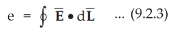
Let us consider Faraday's law. The induced e.m.f. is a scalar quantity measured
in volts. Thus the induced e.m.f. is given by,
•
The induced e.m.f. in equation (9.2.3) indicates a voltage about a closed path
such that if any part of the path is changed, the e.m.f. will also change.
•
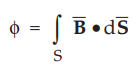
The magnetic flux ϕ passing through a specified area is given by
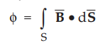
where B = Magnetic flux density
•
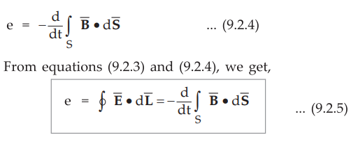
Using above result, equation (9.2.2) can be rewritten as
•
The variation of flux ϕ with respect to time t can be caused due to any one of
the following conditions.
a)
By having a stationary closed path in a time varying ![]() field.
field.
b)
By having a time varying closed path in a static ![]()
c)
By having a time varying closed path in a time varying ![]() field.
field.
•
When an e.m.f. is induced in a stationary closed path due to time varying B
field, the e.m.f. is called statically induced e.m.f. or transformer e.m.f.
When the e.m.f. is induced in a time varying closed path due to a static ![]() field, the e.m.f. is called dynamically induced e.m.f. or motional
e.m.f.
field, the e.m.f. is called dynamically induced e.m.f. or motional
e.m.f.
1. A Stationary Closed Path in a Time Varying  Field -
Statically Induced E.M.F. or Transformer E.M.F.
Field -
Statically Induced E.M.F. or Transformer E.M.F.
•
The condition in which a closed path is stationary and the magnetic field ![]() is varying with time is as shown in the Fig. 9.2.1.
is varying with time is as shown in the Fig. 9.2.1.

• A closed circuit stationary, while a magnetic flux density varying with time.
•
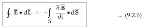
The closed circuit in which e.m.f. is induced is stationary and the magnetic
flux is sinusoidally varying with time. From equation (9.2.5) it is clear that
the magnetic flux density is the only quantity varying with time. We can use
partial derivative to define relationship as ![]() may be changing with
the co-ordinates as well as time. Hence we can write,
may be changing with
the co-ordinates as well as time. Hence we can write,
•
This is similar to transformer action and e.m.f. is called transformer e.m.f..
Using Stake's theorem, a line integral can be converted to the surface integral
as
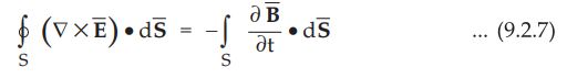
Assuming
that both the surface integrals taken over identical surfaces.
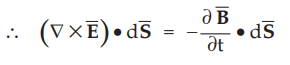
Hence
Finally
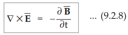
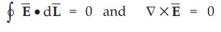
•
Equation (9.2.8) represents one of the Maxwell's equations. If ![]() is
not varying with time, then equations (9.2.6) and (9.2.8) give the results
obtained previously in the electrostatics.
is
not varying with time, then equations (9.2.6) and (9.2.8) give the results
obtained previously in the electrostatics.
2. A Moving Closed Path in Static Field - Dynamically
Induced E.M.F. or Motional E.M.F.
The
condition in which magnetic field ![]() is stationary while a closed path is moving
or revolving is as shown in the Fig. 9.2.2.
is stationary while a closed path is moving
or revolving is as shown in the Fig. 9.2.2.
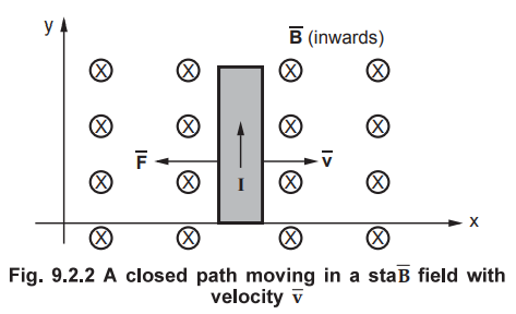
•
Secondly magnetic field is stationary, constant not varying with time while the
closed circuit is revolved to get the relative motion between them. This action
is similar to generator action, hence the induced e.m.f. is called motional or
generator e.m.f.
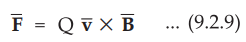
•
Consider that a charge Q is moved in a magnetic field ![]() at a velocity
at a velocity ![]() . Then the force on a charge is given by,
. Then the force on a charge is given by,
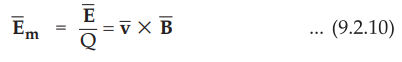
•
But the motional electric field intensity is defined as the force per unit
charge. It is given by,
•
Thus the induced e.m.f. is given by
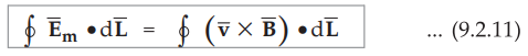
•
Equation (9.2.11) represents total e.m.f. induced when a conductor is moved in
a uniform constant magnetic field.
•
If the directions of velocity ![]() with which conductor is moving and
the magnetic field
with which conductor is moving and
the magnetic field ![]() are mutually perpendicular to each other,
then the induced e.m.f. is given by,
are mutually perpendicular to each other,
then the induced e.m.f. is given by,
e
= Blv sin90° = Blv ... (9.2.12)
where l = Length of straight conductor.
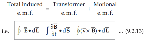
3. Moving Closed Path in a Time Varying Field
•
A moving closed path in a time varying B field represents a general case in
which both the e.m.f.s i.e. transformer e.m.f. and motional e.m.f. are present.
Thus the induced e.m.f. is the combination of two e.m.f.s. Hence the induced
e.m.f. for a moving closed path in a time varying field ![]() can be
expressed as,
can be
expressed as,
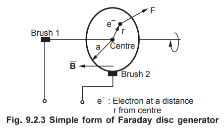
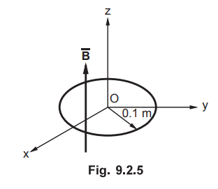
4. Faraday's Disc Generator
•
A Faraday disc generator consists a rotating disc, with its axis located
horizontally. This disc is placed in uniform magnetic field ![]() . To make
the contact with the disc, two brushes are used. One of the brushes is located
at the rim while the other brush is located at the axis as shown in the Fig.
9.2.5.
. To make
the contact with the disc, two brushes are used. One of the brushes is located
at the rim while the other brush is located at the axis as shown in the Fig.
9.2.5.
•
Assume that the magnetic field ![]() is along the axis of the disc. In
other words, the magnetic field is perpendicular to the plane of the disc. Let
a be the radius of the disc. Assume that the disc is rotated at constant
angular velocity ro expressed in rad/sec. Consider that an electron is located
at a distance r from the centre of the disc C.
is along the axis of the disc. In
other words, the magnetic field is perpendicular to the plane of the disc. Let
a be the radius of the disc. Assume that the disc is rotated at constant
angular velocity ro expressed in rad/sec. Consider that an electron is located
at a distance r from the centre of the disc C.
•
As the disc rotates at an angular velocity ro rad/sec, the electron moves at a
velocity which is given by,
v
= ωr m/s
•
Thus the force exerted on electron is given by,
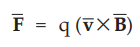
where
q is charge on electron.
•
But the electric field intensity can be written as,
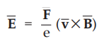
•
Thus the magnitude of the electric field intensity is given by,
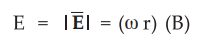
•
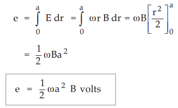
The field acts radially inwards. Thus e.m.f. produced between centre of the
disc and rim of the disc is given by,
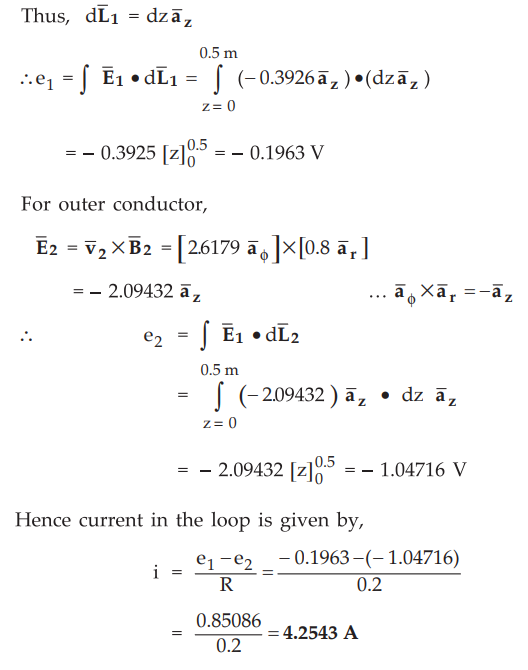
Ex.
9.2.1 A rectangular conducting loop with a resistance of 0.2 Ω rotates at 500
r.p.m. The vertical conductor at rr = 0.03 m is in the field 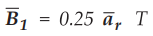 and other conductor is at r2 = 0.05 m and in the field
 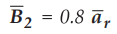 T. Find
current flowing in the loop.
T. Find
current flowing in the loop.
Sol.
:
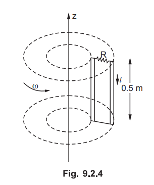
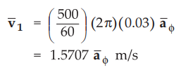
The
inner conductor which is at r1 = 0.03 m rotates at 500 r.p.m. Thus
inner conductor rotates with 500 / 60 revolutions per second. As in one second,
the distance covered is (2 π r) meter, for the inner (500/60) (2 π r) meters. Then the linear velocity for inner
conductor is given by
Similarly
for outer conductor, linear velocity is given by
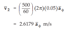
=
2.6179 a m/s
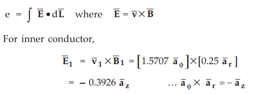
Here ![]() is not varying with time, it is constant in
is not varying with time, it is constant in ![]() direction.
Thus under such condition, the induced e.m.f. is given by,
direction.
Thus under such condition, the induced e.m.f. is given by,
Both
the conductors are vertical. Let us assume that length of each conductor be 0.5
m.
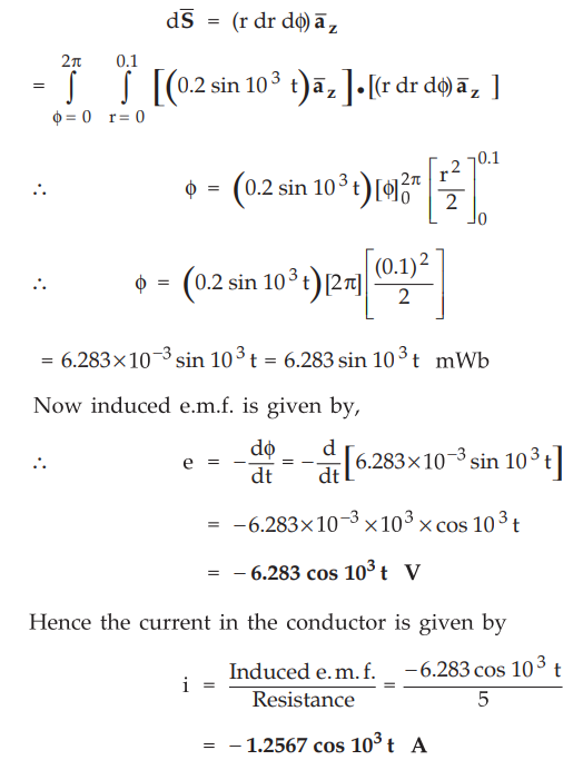
Ex.
9.2.2 A circular loop conductor lies in plane z = 0 and has a radius of 0.1 m
and resistance of 5 Ω. Given  T, determine the current in the
loop.
T, determine the current in the
loop.
AU
: Dec.-14, Marks 8
Sol.
:
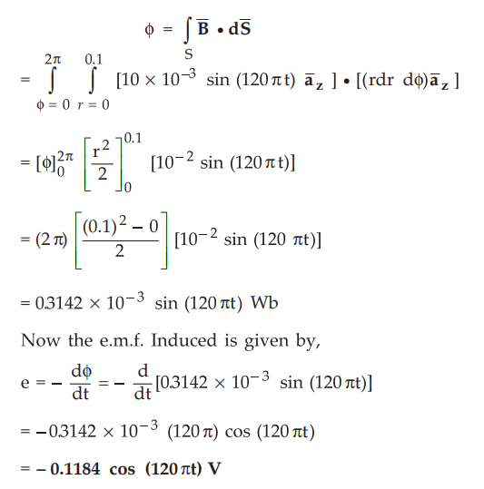
To
find current in the loop, let us first calculate induced e.m.f.
A
circular loop is in z = 0 plane. ![]() is in z-direction which is perpendicular to
the loop. So
is in z-direction which is perpendicular to
the loop. So ![]() is perpendicular to the circular loop.
is perpendicular to the circular loop.
Hence
total flux is given by
With
cylindrical co-ordinate system,
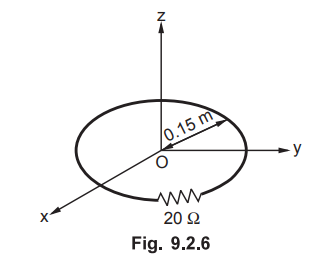
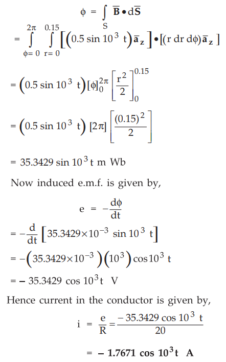
Ex.
9.2.3 The circular loop conductor having a radius of 0.15 m is placed in X-Y
plane. This loop consists of a resistance of 20 Ω as shown in the Fig. 9.2.6. If the magnetic
flux density is  T. Find current flowing through this loop.
AU
: May-17, Marks 7
Sol.
:
The circular loop conductor is in X-Y plane. ![]() is in
is in ![]() direction
which is perpendicular to X-Y plane.
direction
which is perpendicular to X-Y plane.
Hence,
we can write,
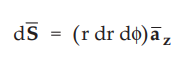
Total
flux is given by
Ex.
9.2.4 A circular loop of wire is placed in a uniform magnetic field of flux
density 0.5 wb/m . The wire has 200 turns and frequency of rotation of 1000
revolutions/minute. If the radius of the coil is 0.2 m, determine (1) the
induced emf when the plane of the coil is 60° to the flux lines and (2) the
induced emf, when the plane of the coil is perpendicular to the field.
AU
: Dec.-15, Marks 8
Sol.
: The
velocity of circular loop is given by
V
= (1000 / 60) (2 πr) m/s = (1000 / 60) (2 π
× 0.2) = 20.944 m/s
1)
Now the angle made by plane of coil to the flux lines is 60Ω i.e. θ =
60 Ω . Hence induced emf is given by,
e = Blv sin θ = B[(2πr)N] v sin θ
=
0.5[(2 π × 0.2)(200)](20.944)sin60° = 2.2793 kV
2)
When plane of coil is perpendicular to flux lines,
θ
= 90,
e
= e = Blv sin 90° = e = Blv
=
(0.5)(2 π × 0.2 × 200)(20.944) = 2.632 kV
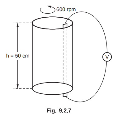
Ex.
9.2.5 A conducting cylinder of radius 7 cm and height 50 cm rotates at 600
r.p.m. in a radial field 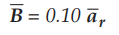 T. Sliding contacts at the top and bottom
are used to connect a voltmeter as shown in the Fig. 9.2.7. Calculate induced
voltage.
T. Sliding contacts at the top and bottom
are used to connect a voltmeter as shown in the Fig. 9.2.7. Calculate induced
voltage.
Sol.
:
A conducting cylinder rotates in the direction as shown in the Fig. 9.2.7. It
rotates at 600 r.p.m. Means in 1 sec there are 10 revolutions. The radius of
the cylinder is 0.07 m. In 1 revolution, the distance travelled by the cylinder
is (2 πr)
m i.e. (2 × π × 0.07) m. Hence in 10 revolutions, it travels (2
× π
× 0.07 × 10) m distance. So the linear velocity is given by,
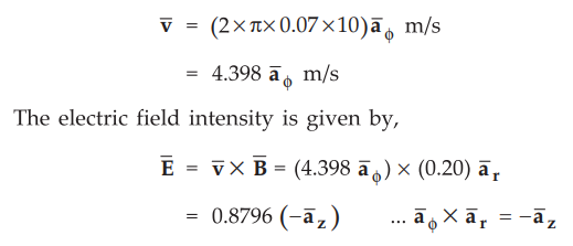
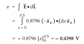
Here
field is not varying with time. The cylindrical conductor is rotating. Each
vertical element of it on the curved surface cuts same flux and thus the
induced voltage is same. As these elements are as if in parallel, the e.m.f.
induced in one element is same as that total e.m.f.
Ex.
9.2.6 A conductor of length 0.5 m moves in a uniform magnetic field of density
1.1 T at a velocity of 30 m/s. Calculate the induced voltage in the conductor
when the direction of motion is perpendicular to the field.
AU
: May-04, Marks 2
Sol.
:
The induced e.m.f. is given by,
e
= Blv sin θ = (1.1) (0.5) (30) sin π / 2 = 16.5 V
As
field and direction of motion are perpendicular to each other, θ = π / 2
Ex.
9.2.7 A conductor 1 m in length is parallel to the z-axis and rotates at 1500
rev/mm with radius of 25 cm. Find the induced voltage if the radial field is 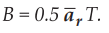
AU
: May-95, Dec.-19, Marks 6
Sol.
:
Here the magnetic flux is constant while the path is rotating with speed of
1500 r.p.m. The field intensity is given by,

In one minute there are 1200 revolutions which
corresponds to 20 revolutions in one second. The distance covered in one second
is (2 πr)
meter. Hence in 20 revolutions the
distance travelled is (40 πr) meter. The conductor rotates in
ϕ direction. Hence linear velocity is given by,
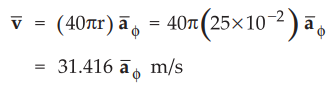
Hence
the electric field intensity is given by,
Ex.
9.2.8 The total flux at the end of a
long bar magnet is 300µWb. The end of the bar magnet is drawn through a 1000
turn coil in 1/100 seconds. What is the e.m.f induced in the coil ?
AU
: Dec.-97, Marks 4
Sol.
:
The induced e.m.f in the coil is given by,
e
= N (d ϕ
/ dt) = N (change in flux/ change in time)
=
(1000) 300 × 10-6 / (1/1000) = 30 V
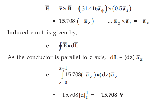
Ex.
9.2.9 Calculate the induced e.m.f. at t = 10 sec. when the flux through each
turn of a 200 turn coil is t (t-1) mWb.
AU
: May-07, Marks 4
Sol.
:
Ex.
9.2.10 A conducting loop of radius 10 cm lies in the z = 0 plane.
The
associated  . Calculate the voltage induced in the loop.
AU
: May-14, Marks 5
Sol.
:
Given : r = 10 cm = 10 × 10-2m,
A
conducting circular loop is in z = 0 plane and ![]() is in z-direction
which is perpendicular to loop. Hence
is in z-direction
which is perpendicular to loop. Hence ![]() is perpendicular to the loop.
is perpendicular to the loop.
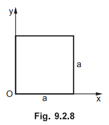
Ex.
9.2.11 A square loop of side a lies in the xy plane as shown. A magnetic field
exists in the region directed along the z direction and varies with time and
space as 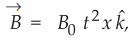 where B0 is appropriately dimensioned.
Calculate
the emf developed in the loop. If the x component of the induced electric field
is zero, obtain an expression for the electric field induced and show that the
line integral of the electric field correctly gives the emf calculated.
AU
: Dec.19, Marks 15
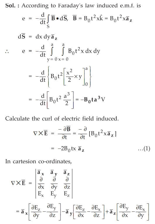
Sol
. :
Now
x component is to be made zero and equating z component with equation (1)
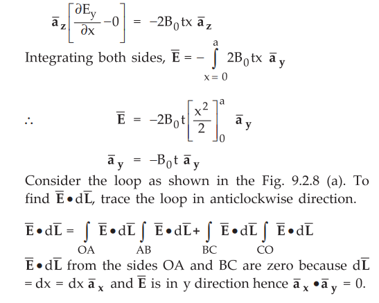
The
contribution by CO is also zero as x = 0 for this line and hence E = 0. The
only contribution is from AB with x = a.
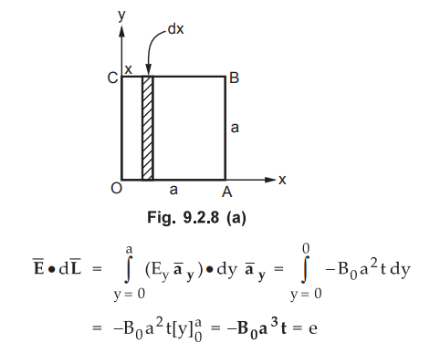
Thus
the line integral of the electric field intensity correctly gives the e.m.f.
calculated.
Examples
for Practice
Ex.
9.2.12 Determine the e.m.f. induced about the
path r = 0.5, z = 0, t = 0 .
[Ans.:
- 2.9609 V]
Ex.
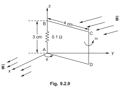
9.2.13 A loop shown in the Fig. 9.2.9 is
inside a uniform magnetic field
If side d.c. of the loop cuts flux lines at
frequency of 50 Hz and the loop lies in the y-z plane at t = 0, find
i)
the induced e.m.f. At t = 1 ms.
ii)
the induced current at t = 3 ms.
[Ans.:
5.8248 mV, 0.15249 A]
Ex.
9.2.14 An area oj 0.65 m2 in the
plane z = 0 encloses a filamentary conductor. Find the induced voltage if
[Ans.:
22.98 sin 103t V]
Review Questions
1. State and explain
Faraday's law of electromagnetic induction.
2. Explain following
i) Motional e.m.f. ii)
Transformer e.m.f.
3. Define the
Faraday's laws. What are the different ways of e.m.f. generation? Explain with
the governing equations and suitable example for each.
AU : Dec.-08, 03,
Marks 16
4. What are the
different ways of e.m.f. generation? Explain with the governing equations and
suitable practical examples.
5. Write short note on
Faraday’s law of electromagnetic induction.
6. Explain the concept
of emf induction in static and time varying magnetic field.
Electromagnetic Theory: Unit IV: Time Varying Fields and Maxwells Equations : Tag: : - Faraday’s Law and Lenz’s Law
Related Topics
Related Subjects

Electromagnetic Theory
EE3301 3rd Semester EEE Dept | 2021 Regulation | 3rd Semester EEE Dept 2021 Regulation