Electron Devices and Circuits: Unit V: (b) Oscillators
Hartley Oscillator
Transistorised, Derivation of Frequency, Advantages, Disadvantages, Applications, Equivalent Circuit, Solved Example Problems
• It uses two inductive reactances and one capacitive reactance in its feedback network. Depending on the active device used in amplifier stage, the two types of Hartley oscillators are, i) BJT Hartley oscillator ii) FET Hartley oscillator.
Hartley Oscillator
AU
: May-04, 10, 13, 17, Dec.-10, 11, 12, 13, 14
•
It uses two inductive reactances and one capacitive reactance in its feedback
network. Depending on the active device used in amplifier stage, the two types
of Hartley oscillators are,
i)
BJT Hartley oscillator ii) FET Hartley oscillator.
1. Transistorised Hartley Oscillator
•
The Fig. 10.9.1 shows the practical circuit of Hartley oscillator using BJT as
an active device. The resistances R1 R2 and RE
are the biasing resistors.
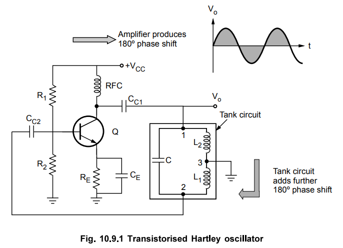
•
The RFC is radio frequency choke whose reactance value is very high at high
frequency and can be treated as open circuit. While for d.c. operation, it is
shorted hence does not cause problems for d.c. operation.
•
Due to RFC, the isolation between a.c. and d.c. operation is achieved. The Ccl
and CC2 are the coupling capacitors while CE is the emitter bypass capacitor.
The CE amplifier provides phase shift of 180°.
•
In the feedback circuit, as the centre of Ll and L2 is grounded, it provides
additional phase shift of 180°. This satisfies Barkhausen condition. In this oscillator,
•
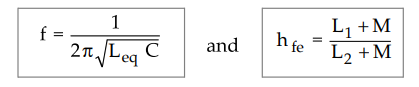
The inductance Li + L2 is equivalent inductance denoted as Leq. To satisfy I
API = 1, the hfe of the BJT used must be L1/L2.
Hfe
= L1 / L2
•
Practically Li and L2 are wound on a single core and there exists a mutual
inductance M between them. The circuit is shown in the Fig. 10.9.2.
In
this case, Leq = L1
+ L2 + 2M
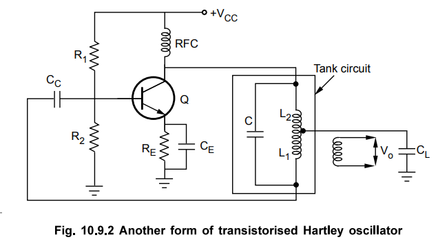
•
If capacitor C is kept variable, frequency can be varied over wide range.
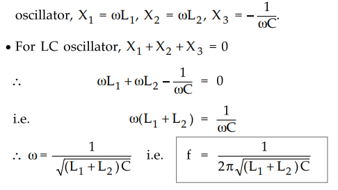
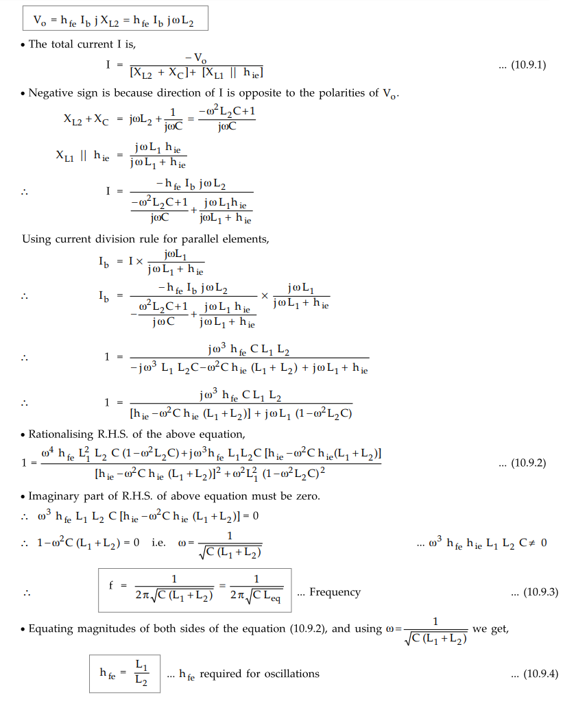
2. Derivation of Frequency of Oscillations
• The output current is collector current which is hfe Ib' where Ib is base current. Assuming coupling capacitors shorted, the capacitor C gets connected between collector and base.
•
As emitter is grounded for a.c. analysis, L1 is between emitter and base while
L2 is between emitter and collector. The equivalent circuit is shown in the
Fig. 10.9.3.
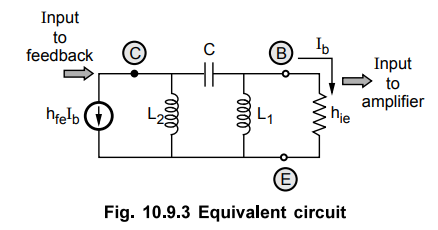
•
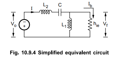
hie is the input impedance of the transistor. The output current is
Ib while input current is hfe Ib- Convert current source to voltage
source as shown in the Fig. 10.9.4.
•
In practice, and L2 may be wound on a single core so that there exists a mutual
inductance between them denoted as M.
•
In such a case, the mutual inductance is considered while determining the
equivalent inductance Leq. Hence,
Leq
= L1 + L2 + 2 M
•
If L1 and L2 are assisting each other then sign of 2M is
positive while if L-^ and L2 are in series opposition then sign of 2M is
negative.
•
The expression for the frequency of the oscillations remain same as given by
equation (10.9.3).
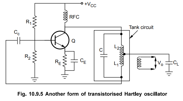
•
A practical circuit where the mutual inductance exists between L1 and L2, of
transistorised Hartley oscillator is shown in the Fig. 10.9.5.
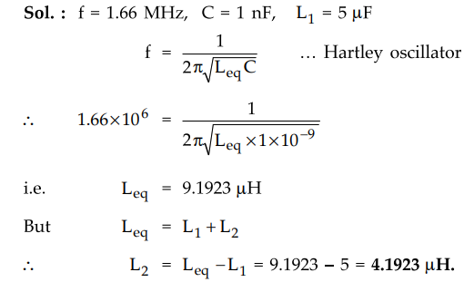
Ex.
10.9.1 A Hartley oscillator is found to oscillate at 1.66 MHz. The oscillator
uses a capacitor of 1 nF in tuned circuit. If one of the inductors in tuned
circuit is 5 pH, find the value of other inductor.
Sol.
:
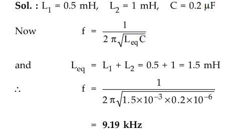
Ex.
10.9.2 Calculate the frequency of oscillations of a Hartley oscillator having =
0.5 mH, =1 mH and C = 0.2 μF.
Ex.
10.9.3 In a transistorised Hartley oscillator the two inductances are 2 mH and
20 pH while the frequency is to be changed from 950 kHz to 2050 kHz. Calculate
the range over which the capacitor is to be varied.
Sol.
:
The frequency is given by,
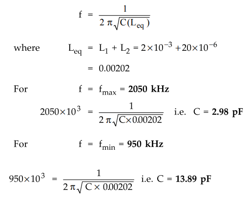
Hence
C must be varied from 2.98 pF to 13.89 pF, to get the required frequency
variation.
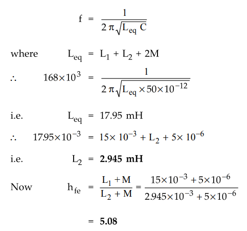
Ex.
10.9.4 In a Hartley oscillator, LI = 15 mH and C = 50 pF. Calculate
L2 for a frequency of 168 kHz. The mutual inductance between L1
and L2 is 5 pH. Also find the required gain of the transistor to be
used for the oscillations.
Sol.
:
For a Hartley oscillator,
3. Advantages, Disadvantages and Applications
•
The advantages are,
i)
The frequency can be easily varied by variable capacitor.
ii)
The output amplitude remains constant over the frequency range.
iii)
The feedback ratio of L1 to L2 remains constant.
iv)
It can be operated over wide range of frequency.
•
The disadvantages are,
i)
The output is rich in harmonics hence not suitable for pure sine wave
requirement.
ii)
Poor frequency stability.
•
The applications are,
i)
Used as local oscillator in T.V. and radio receivers.
ii)
In function generators.
iii)
In radio frequency sources.
Review Questions
1. Draw and explain the operation of a Hartley oscillator. Derive
the equation for fr and hfe.
AU : May-04, 10, 13, 17, Dec.-l0, 11, 18, Marks 16
2. Draw the circuit diagram and explain the principle of
operation of Hartley oscillator.
AU : Dec.-12, 13, 14, Marks 8
3. A Hartley oscillator circuit has C = 500 pF, L1 = 20 µH and L2
= 2 mH. Find the frequency of oscillations.
(Ans.: 45.01 kHz)
4. In a Hartley oscillator Lj =20 qH, = 2 mH and C is variable. Find the range of C if frequency is to be
varied from 1 MHz to 2.5 MHz. Neglect mutual inductance.
(Ans.: 2.0244 pF to 12.6525 pF)
Electron Devices and Circuits: Unit V: (b) Oscillators : Tag: : Transistorised, Derivation of Frequency, Advantages, Disadvantages, Applications, Equivalent Circuit, Solved Example Problems - Hartley Oscillator
Related Topics
Related Subjects

Electron Devices and Circuits
EC3301 3rd Semester EEE Dept | 2021 Regulation | 3rd Semester EEE Dept 2021 Regulation